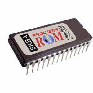
Installing a Chip on the 1993-1995 BMW 325i/525i
This document is about installing a performance chip on a 1993 – 1995 BMW 325i or 525i ECU (Motronic DME).
E36 Model
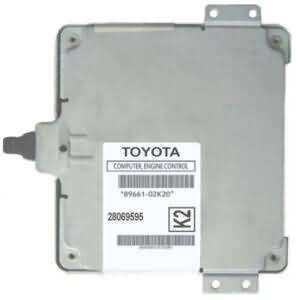
First of all, you will need to locate the DME and uninstall it from the car. The DME is located under the hood, in the engine compartment, below the right wiper assembly (passenger side).
#1
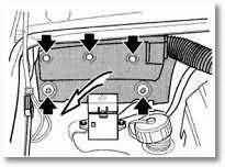
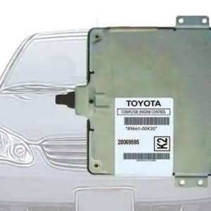
Refer to the drawing above. At the upper right corner of the vehicle (passenger side), which really is the upper left corner if you are looking from the front of the vehicle and facing towards the windshield, you will see a soft foam cover. Remove the three black plastic buttons that are on top, and pry out the plastic tab centers to remove the buttons, and then remove the insulated foam cover.
#2
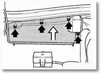
Now, you will see a hard plastic cover. Remove this cover by removing the four top screws.
#3
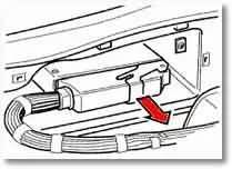
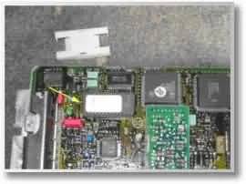
You will find the DME box attached to a wire harness. Remove it by pulling it out. The DME will just slide out.
Do not disconnect the harness until the DME is completely removed. For disconnecting the harness, just pull out the lock lever in the direction shown by the red arrow in the picture above.
Interested in the full wiring diagram of the ECU connections of the 1994-1995 BMW 325i 2.5L?
(ALWAYS check your SPAM folder in case that you don't see the download in your inbox.)
Your information is safe with us. We take privacy seriously and DO NOT sell or share your information in any way.
Your data will only be used for sending the requested document(s) and for emailing any related information or material that we might offer in any future. If we do so, you will always be provided with a link for unsubscribing if you desire to do so.
E34 Model
#4
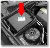
If your BMW is the E34 chassis model, the DME is located under a plastic cover, as shown by the red arrow in the picture above.
Chip Installation
Now with the DME on a bench, there are six tabs holding the DME at the bottom of it. Using a small and sharp flat screwdriver, CAREFULLY bend the tabs away, so you can take the cover out of its place. Take extra precaution here, as the tabs are made of aluminum and are brittle and fracture very easily. The same when you finish and are putting it back together and folding it back in place.
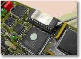
Now, inside of the DME, there is a white plastic cover on top of the EPROM chip. It looks like an “H” (picture below). The chip underneath that plastic cover is the chip to be replaced, so unsnap the plastic cover and, BEFORE removing the chip, please notice the alignment of pin #1, so the new chip can be inserted the same way (see a note about this at the end of this article).
Take out the chip by using the flat screwdriver and slide it carefully under the chip for slowly prying it out of place, little by little, from both sides, one at a time. If you have a simple chip pulling tool, you may use it instead. When prying the chip upwards, be careful not to break the plastic socket where the chip is inserted.
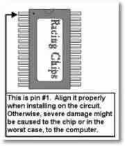
Now install the performance chip by inserting it into the socket. To do this, align pin #1 to the same corner as the old chip had pin #1, then carefully align all the pins into the holes and push it down firmly or gently tap repeatedly over it. Reinsert the plastic “H” shaped plastic cover. Now you are ready to put back the DME cover, reinstall the DME in your car, and enjoy the new performance.
The Right Orientation of The Chip
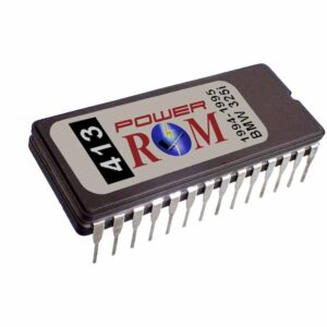
Need a great chip for your 1994-1995 BMW 325i? The chip in the link below is for the Bosch 0 261 200 413 DME (ECM). Its performance compares with top-selling chips on the market from big names.

Related Articles:
Engine problems after touching the battery terminal with the ECM of my 1994-1995 BMW 325i


Thanks for post. Nice to see such good ideas.
Hey I bought one of those from racingchips. They are just great. It has my 325i pulling hard now. thanks!
sorry, I had a question about the chip on racingchips.net. Will post it in the right page. Thanks
Henry, I’m glad you could take advantage of our advice.
Neftali, no problem. As soon as you post your question, we will be more than glad to help.
Regards,
Richard
Hi, good post. I have been wondering about this issue,so thanks for posting. I’ll definitely be coming back to your site.
Very nice post 🙂 Thank you for sharing
Good Information. Is it the same procedure for 2001 325i?
No. This doesn’t apply for any 1996 and later BMW models. Those OBD-II models does not have a replaceable chip like earlier OBD-I models do.
There are places that sell for the BMW 2001 325i on eBAY. Your 1996 look somewhat similiar to my 2001. I think the third diagram look familiar.
Yes, the circuits might look similar, but unfortunately the chip depicted here is not available in the 2001 model’s computers.
On eBay what they offer are mostly resistors in a box, unless they are selling a reprogrammable unit, not just a box with 2 to 6 wires attached to it.
The reprogramming approach for these ecus is different and will include using special hardware and equipment.
Okay I think you enlighten me. There are chipa and there are resistors.
Do resistors act the same as chips??
No, not at all. You will find interesting the following article on this blog:
Resistors Vs Chips
Regards,
Richard
wow sweet stuff dude.