How Chip On Board (COB) Circuits are Assembled
If you like to open electronic devices when they get damaged, either to try to fix it or to use it for spare electronic parts or just to take a look inside, out of curiosity to see how it is built or what is inside, you might see in some devices a black “dot” chip which seems to be part of the circuit board. Some call it the “black dot”, some others call it “epoxy chip” and there are several other names, but the correct name is “Chip On Board” or COB.
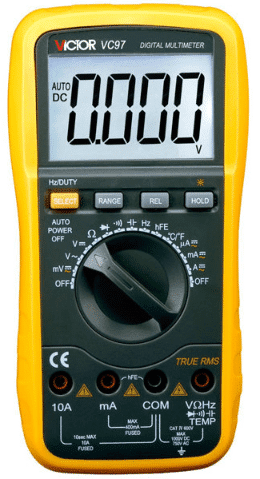
These COB chips are in most cases a Micro Controller Unit (MCU), but it can also be memory or any other complex circuit, either digital, analog, or a combination of both. You can find it in electronic toys, or maybe in that sound postcard that you bought as a present for someone, or in electronic tools like multimeters. You may find it anywhere where a complex circuit is needed but space is limited.
I always thought of how do they make these COBs. How are they assembled within the circuit? I could kind of imagine the process, but nothing like watching how they exactly do it.
Well, I found an article on the Sparkfun.com website about someone who was permitted to take pictures and videos inside the “Victor” factory in China. This factory produces among other things, electronic test equipment, like multi-meters.
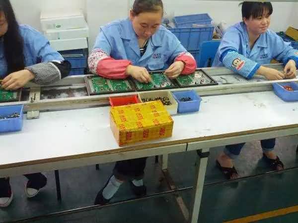
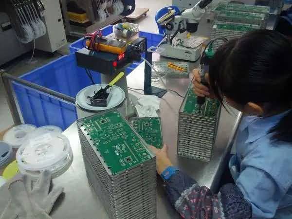
The first picture you will see is the assembly line where workers are installing some parts in the circuit boards. I’m not sure if this is done before or after installing the COB chip in the circuit.
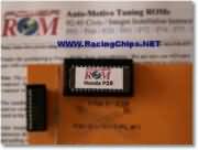
In the picture below you will see a container where the chips to be used as COB are received in the factory. As you can see, there are 100 chips in a single container. These are outsourced from another company with the specifications that the Victor company requests. They do not manufacture the chip, but it is their design.
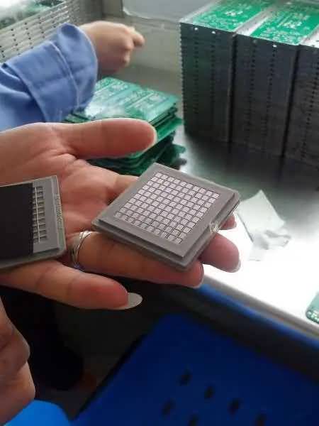
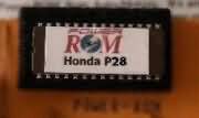
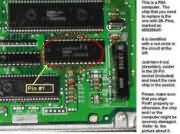
The chips are completely flat, as you can see in the picture above. No leads are coming out of it. So how does this connect to the rest of the circuit in the circuit board? They glue the chip in place on the circuit board first and when the glue sets, they use a machine to spot weld each one of the leads from the chip surface, down to the circuit board contacts.
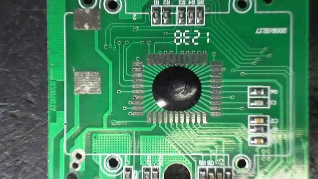
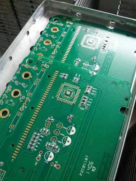
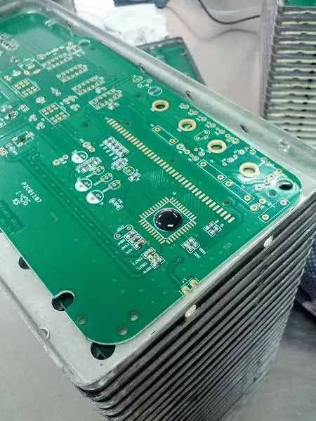
Below you can see a circuit boards with the COB chips already glued to it.
Spot welding (or bonding) can be seen in the two videos below. As they explained, it seems to be that it is not a conventional spot welding process nor soldering, but a bonding process, that is done by using different types of energy combined, like ultrasound, heat, and mechanical pressure.
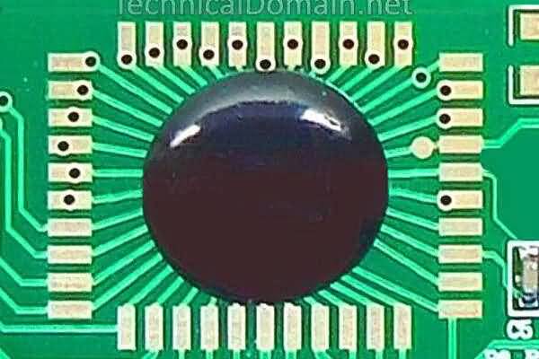
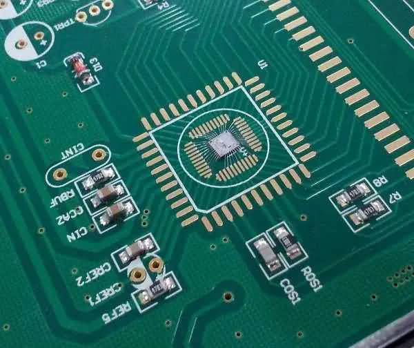
Below is the COB chip already glued and with its leads bonded to the circuit board.
The final step is to put “The Black Dot”! They manually cover the COB chip with some substance similar to epoxy resin, to protect the chip and its leads. I say “epoxy” to invoke some similarity, but the truth is that it feels like ceramic to the touch. So what they use is something similar to epoxy, but definitively harder. Maybe a specific mixture of epoxy and other materials.
You can access the original article on Spakfun.com by clicking on the link below:


PCB,COB CHIPS music & voice AUTO SEALING MACHINE
I Want cob ic chips music & voice cob PCB, AUTO SEALING MACHINE
Hi
My requirement cob chip on board wire bonding assembly service
91+8788980040