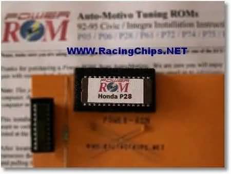
Installing a Honda P28 ecu chip
While this covers installing a chip on the USDM version (US Domestic Market) Honda P28 ECM, the procedure is the same for almost all 1992-1995 (OBD-I) Civic and Integra ECMs. All of them use the same circuit construction. These include, but are not limited to, the Honda P05, P06, P08, P28, P30, P72, P75, and PR4 (OBD-I version).
This requires electronic component soldering skills, especially when working with these ECM circuits, which are sensitive to overheating during soldering and unsoldering. Also, you may find it somewhat difficult to desolder parts from these circuit boards because of their multi-layer structure. Multi-layer means that it has connections above, below, and inside the top and bottom circuit board layers.
First, uninstall the ECM from your car. It is located beneath the carpet in the passenger’s side footrest.
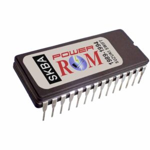
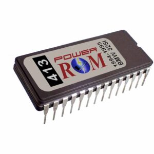
After you uninstall the ECM, place it on a bench or flat table to work on it. Have all the parts in the kit handy: the Power-ROM chip, the 1K resistor, the two 0.1uf capacitors, the 74HC373 chip, and a wire jumper. The jumper can be any piece of thin wire. A short length cut from the resistor lead will do the job.
Needed tools
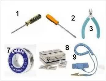
1- A Phillips #2 screwdriver (for removing and replacing the ECM covers)
2- A small flat screwdriver (for prying the chip out of the socket if needed)
3- Small wire cutters or clippers (for cutting excess length of component leads)
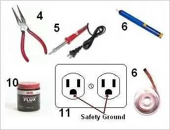
4- Long-nose pliers (For holding the small parts when installing)
5- 35-watt soldering iron (for soldering/desoldering the parts in the circuit)
6- Desoldering vacuum tool or desoldering braid (for removing parts and cleaning connections)
7- 60/40 rosin core solder
8- Alcohol pads (for cleaning the circuit board from excess soldering flux)
9- Anti-static wrist (for protecting the ECM from static electricity)
10- Soldering flux (liquid or paste, for electronic soldering – DO NOT use plumbing or any acid flux)
Before starting, plug in the soldering iron so it’s ready to use in a few minutes. Also, put on the anti-static wrist strap and connect the other end to an earth ground, like a metal conduit on the household electrical circuit. Check #11 of the drawing above for using the household electrical circuit for this. This will protect the ECM and the components you install. Static electricity may be high enough to damage the ECM if it ever receives a discharge from you.
Start by removing all 10 bolts (5 on each side) that hold the ECM covers. For the rest of the process, please refer to the drawing below:
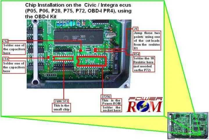
On the component side of the circuit board, look for the footprint marks on the circuit where the parts belong. You will find six footprints in the lower-right corner of the ECM if it is in the same position as in the picture above. The six footprints are: “27256“, “74HC373“, “R54“, “C51“, “C52“, and “J1“.
If your ECM hasn’t been “chipped” before, you will find the connections on those footprints covered with solder, but no components installed. Otherwise, some components may already be in place. In that case, if a socket is installed for inserting the chip, your job will be to pull the installed chip (if any) and insert the new chip.
On the other hand, if the ECM has a factory-installed chip, normally done by Honda in some ECMS as a modification for converting from one ECM type to another, then the chip to be replaced will have a copper-colored label on it and will NOT be mounted on a socket.
In the two cases described above, the “OBD-I Kit” will not be needed, except for the socket in the factory chip case. The factory chip case is the most difficult because, as mentioned earlier, the factory chip will be soldered with no socket and will have to be removed (desoldered) to be replaced with the kit’s 28-pin socket. Removing a directly soldered chip is not the easiest job on these models because of the already-mentioned sensitivity to heat. If, at any point after inspecting the job, you don’t feel like doing it, I suggest taking it to a professional.
If you think you can do it yourself and decide to do so, one trick for desoldering the chip that can help is to first re-solder all the pins of the chip with excess solder to “rejuvenate” the connections. This makes it easier for the solder to flow when you pull it out with the soldering iron and a desoldering vacuum tool.
Desoldering braid will not be very effective for removing the chip. It is used to clean the board by removing solder from connections once the parts are removed, and to open them for inserting new parts.
This job takes great care and patience, so please take your time to do it right, because although many accidents can be repaired, if an internal connection of the board happens to get broken somehow, whether it be because of too much heating or because of too much force pulling the chip, it might be as bad as needing to replace the ECM.
To clear the connections for inserting the components, apply solder flux to the connections on the circuit and remove the solder using a soldering iron with either a desoldering vacuum tool or desoldering braid.
The connections on the board should remain open, and you should be able to look through the holes after the solder is correctly removed. After you finish all footprints for the marked components, clean the circuit of excess soldering flux with the alcohol pads.
Installing the parts
After cleaning all pin-connection areas with alcohol, install the corresponding part on each footprint by soldering it to the circuit. Remember to install the 28-pin socket instead of soldering the power-ROM directly to the “27256” footprint, and make sure the socket’s pin #1 marking is oriented correctly to use as a reference when inserting the chip. Care must be taken when soldering the “74HC373” chip, not to (1) overheat it when soldering and (2) not to install it backward, so take note of pin#1 of the “74HC373” chip too.
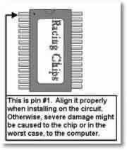
After installing all six parts and inserting the Power-ROM in the socket, just put the ECM back together and reinstall it in your car.
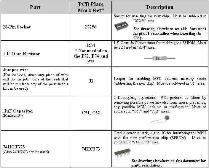
The following table lists the parts in the installation kit and their reference numbers on the circuit board, along with a brief explanation of their function in the circuit. Use it as a reference to make location and installation easier.
If Have Problems
If the engine does not go over 3300-4000 RPMs after installing any chip, something went wrong, either with the installation or the chip was not good or not compatible with your ECM. You will find a troubleshooting guide in the link below should you have problems with your installation.
Troubleshooting Honda P28 Chip Installation