Troubleshooting a Honda P28 Chip Installation
Did you install a performance chip in a Honda P28 ECM, and it isn’t working? Having problems?
This is more common than you think, since many people install a chip themselves, even without experience soldering electronic parts. But even professionals can run into this, so let’s see what you can do to troubleshoot the problem.
Functions of the Added Parts
The installation involves adding parts to the ECM circuit, and sometimes mistakes happen.
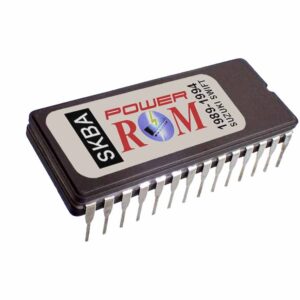
The parts added to the circuit are: two capacitors (for filtering electronic noise), a resistor for powering the “external memory mode” of the MCU, the new EPROM chip (inserted into a 28-pin preinstalled socket), a small 20-pin chip (74HC373 Latch to address low and high memory pages by multiplexing), and a jumper (J1). The jumper “J1” turns the new chip on or off. Since it is in series with the “external memory” activation resistor “R1”, installing the jumper enables the newly installed chip, and removing it disables it, just like a switch. You can install a switch instead of “J1” to externally switch between “power” and “stock” modes.
Basic Troubleshooting Method
This article covers not only the Honda P28, but also the Honda P05, P06, USDM P30, P72, P74, P75, and OBD-I PR4 Honda computer family.
We are basing this troubleshooting on simple connection confirmation with a continuity tester or an ohmmeter.
First Step
If your car is not going over 4000 RPMs, it is in “limp mode”, which is a default mode programmed in the ECM to avoid the engine from being damaged if something wrong is detected in the system. So the first step is to cut the “J1” jumper. If everything goes back to normal, the problem is in the chip or its programming. It is either not good or not compatible with the ECM. Many Honda models are similar, but even if they are from the same year, if the trim is different (Civic EX and Civic CX, for example), the program in the ECM might be different, and a chip not meant for it will activate the “limp mode” and will not go over 4000 RPMs.
If all stays the same and the problem persists after cutting or removing the “J1” jumper, then remove the chip from the socket and try again, keeping the “J1” jumper cut. This will rule out any internal short circuit in the EPROM chip. If the problem persists, then go to the next step.
Second Step
Next, check for solder bridges between pins or broken copper traces. Do a visual inspection first. If nothing looks broken or bridged with solder, test the connections pictured in the table below.
The table below shows what connections should have continuity. If any of the points in the table show no continuity, then a line or connection is broken between the two points, and if it is not spotted visually, you may run a wire between both points. For each part of the broken connection, look for the nearest point with continuity and solder from there. If you do this, keep the wire as short as possible and as close to the board as possible. This will prevent the wire from picking up or generating electronic noise.
The pictures below the table are to help identify the three components the table is based on.
Identifying involved components
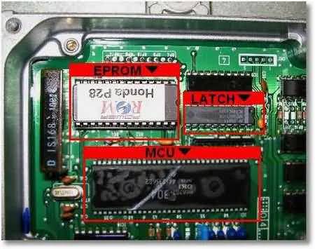
Pin Identification of involved components

Use your ohmmeter or continuity tester to test each of the 28 pins in the table below (left column) against each connection identified in the right column. Also make sure none of the contiguous pins on each of the three chips have continuity (example: pin #1 with pin #2, pin #2 with pin #3, and so on for each of the three chips).
Connections Test Table
| EPROM Check Points | |
| EPROM Pin# | Connects to: |
| 1 | #20 of Latch |
| 2 | #13 of MCU |
| 3 | #15 of Latch |
| 4 | #12 of Latch |
| 5 | #16 of Latch |
| 6 | #19 of Latch |
| 7 | #9 of Latch |
| 8 | #6 of Latch |
| 9 | #5 of Latch |
| 10 | #2 of Latch |
| 11 | #3 of Latch |
| 12 | #4 of Latch |
| 13 | #7 of Latch |
| 14 | #1 & 10 of Latch |
| 15 | #8 of Latch |
| 16 | #18 of Latch |
| 17 | #17 of Latch |
| 18 | #13 of Latch |
| 19 | #14 of Latch |
| 20 | R54 (left side) |
| 21 | #11 of MCU |
| 22 | #23 of MCU |
| 23 | #12 of MCU |
| 24 | #10 of MCU |
| 25 | #9 of MCU |
| 26 | #14 of MCU |
| 27 | #15 of MCU |
| 28 | #20 of Latch |
All the connections in the table should measure continuity (less than 1 ohm) with an ohmmeter or continuity checker. Any reading over 2 ohms indicates a faulty connection.
The only connection that is left out of the table is the following, so please also test this one:
Pin#11 of the HC373, connects to Pin#22 of the MCU
Third and Last Step
If step 1 and step 2 above tests do not reveal the culprit, then the latch 74HC373 chip must be (1) put in reverse or (2) be damaged. If it is damaged, it could have arrived that way, or it could have been damaged by overheating during soldering or by static electricity. In this case, everything will return to normal as soon as you remove that chip from the circuit.
If the 74HC373 chip is bad, it is a common digital chip, and you can order it from many local or online electronics markets. So, by removing the 74HC373 from the circuit and keeping the “J1” jumper cut, you can use your ECM in normal (stock) mode while a new latch chip arrives. You may leave the EPROM chip in the socket, but you must cut the “J1” jumper in the meantime.
F.A.Q
Q – Will a chip with an incompatible program damage my ECU?
A – No. The ECU will turn on the check engine light and go into protection mode (limp mode) to avoid engine damage, but software won’t damage the ECU. To protect the engine, it won’t let it go over 4000 RPM, and the fuel mixture will go very rich to avoid destructive lean conditions.