Dual Performance Chips
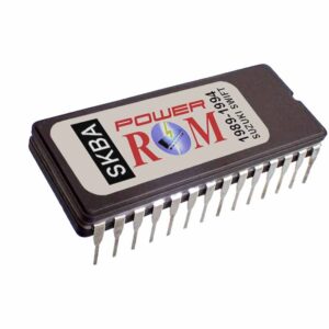
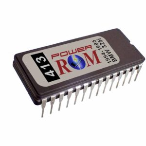
Many performance enthusiasts must have heard or read about dual chips. Dual chips have memory capacity that doubles the original chip’s, so two different, same-size programs can be stored on the new chip and selected on the fly with a small switch.
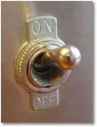
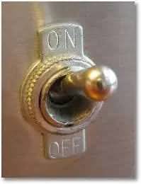
The idea is useful for switching between the stock program and a performance or fuel-economy program. That is, a “Normal” and “Sport” or a “Normal” and “Eco” options switch. Also, if your car doesn’t pass smog tests because of a performance chip you are using, this solution lets you switch to the stock program with the flip of a switch. You can use the stock program on the street, when cruising, and during the inspection, and switch to performance for off-road activity.
If the original chip has enough memory, or the new chip has enough, you can install more “versions ” or “power levels,” but you’ll need more complex switching. We will cover here the dual-program chip only, using a 27C512 (64KB) EPROM, where the original is a 27C256 EPROM (32KB).
If you don’t have, or don’t know how to use or manage, the chip programming equipment, you can ask someone skilled in this to do the burning. If using the “Normal” and “Sports” versions, then you would ask the stock program to be burned in the lower memory page of the chip (0000h-7FFFh) and the performance program in the higher memory page (8000h-FFFFh). This is done by attaching one program to the other in that order, creating a single binary file while doubling the memory space.
Many products do this dual-chip switching. One example is a chip socket with jumpers, averaging $30 to $80, like the Moates product, which is a very nice one.
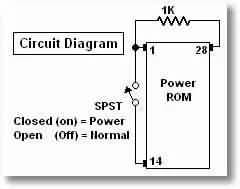
You will just need a 1k-ohm resistor, a small switch, and some thin electrical cable. If you can get a thin shielded 2-conductor wire, the better. That way, you use the switch’s two internal conductors and tie the external shielding to ground. This will prevent the switching wires from picking up electronic noise as an antenna would, which may lock up the MCU in the ECM and cause the uncomfortable situation of needing to turn the ignition off and start the car again. Below is the simple schematic:
Automotive Products, Services, and Articles
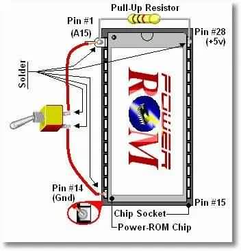
The connection diagram is something like the one below:
Automotive Products, Services, and Articles
Installation
Solder the resistor directly to pins #1 and #28 of the chip. Do this with the chip out of the socket, or you will ruin the socket. Solder must cover only the upper part of the chip leads, or the chip may not reinsert into the socket or may cause false connections. Then wire the switch to lead #1 (carefully, in the same spot as the resistor), and #14 on the upper part of the chip leads, too. Now you can carefully reinsert the chip into the socket, but pin #1 must hang out of the socket, unconnected and not touching any part of the socket’s metal contacts.
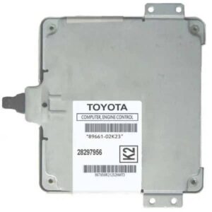
The above is done because pin#1 is used only when programming (writing) the chip, and it is of no use for the ECM (the ECM only reads the chip, it does not write to it), but for some reason, Honda and many other manufacturers wire it directly to the +5V supply of the ECU. This will cause a short circuit if pin #1 is inserted into the socket and WILL damage the ECU when the switch is flipped to the ground position (Pin #14), which corresponds to the “Normal” mode. All this is prevented by leaving the lead of pin#1 hanging, floating out of the socket.
Special Details
Two details apply to this installation.
(1) In some cars, switching on the fly will have no effect. In these cars, for changes to take effect, the car must be turned off, the switch flipped, and then the car turned on again for the second program’s modifications to be available.
This is because in those cars, as soon as they are turned on, the ROM chip is read and transferred to RAM memory, which is faster. That is called ROM shadowing or ROM masking. When the car is turned off and then on, it is forced to re-read the ROM, and with the switch already flipped, it reads the newly selected program and transfers it to RAM.
(2) In most cases, the cables for the switch must not be longer than 12 inches. That is why we recommend installing it in the ECM body instead of the car dashboard. In any case, we recommend a shielded cable, with the shielding connected to ground. Electrical noise can cause the switching of programs to become unstable and turn on the check engine light, or it might also cause the ECU to act erratically or to lock up.
Summary
The method described above is a precise one and has been tested with no problems. It’s an economical option for a simple system like this, but if you don’t have electronics experience or don’t feel comfortable doing it, we recommend taking it to a trained person. A trained person might charge a small fee, but damaging the ECM while trying it yourself can be really expensive.