1993-1995 Accord – Prelude Performance Chip Installation
This applies to the following Honda ECM computers: P0A, P0B, P0C, P0H (OBD-I), P11, P12, P13, and P14
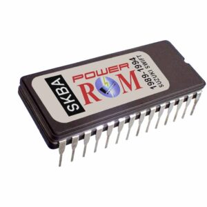
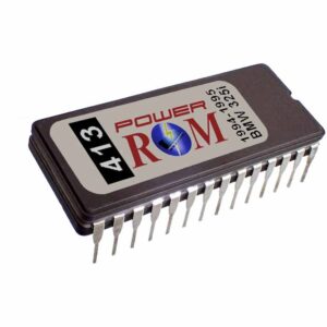
Installing a performance chip on the 1993-1995 Honda Prelude and 1994-1995 Honda Accord is a simple procedure that consists of removing the stock chip, soldering a 28-pin DIL socket in its place, and inserting the performance chip into the socket.
Unlike the OBD-I Civic and Integra ECMs, the OBD-I Accord and Prelude ECMs don’t require installing extra parts beyond the performance chip. They have a stock chip that can be replaced, which makes it simpler in one way but tougher in another, because you will need to desolder the stock chip, which is held in place with solder on the top and bottom sides of the multi-layered circuit board.
This job requires average electronics soldering skills, but if you can not do it, you can bring the computer and the performance chip to any TV shop or electronics-trained technician to install it for you. Verify all connections before and after soldering the 28-pin socket. Be careful not to bridge connections with solder or break circuit traces by overheating the circuit board with the soldering iron. The parts are mounted on a multi-layered circuit board, which is sensitive to excessive heat. Always clean the finished job with alcohol and inspect for potential connection problems before installing the 28-pin socket.
The Honda Accord and Prelude ECMs are located in the passenger-side kick panel. After locating the ECM in your vehicle, remove the bolts that secure it in place and carefully disconnect the wiring harnesses plugged into the ECM terminals. You can disconnect the wiring harnesses by pushing the plastic clip on top of each connector and pulling it back carefully.
This installation is needed only once. Then you can pull out one chip and insert any other, whenever you want to switch between “Stock” and “Power” modes. These instructions cover all 1993 to 1995 (OBD-I) Honda computers that are listed at the top of this page for the Accord and Prelude.
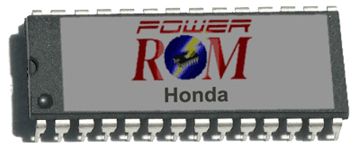
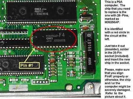
To install the chip, find the 28-pin chip marked “M38256AP-xx” (see the picture below). It must be unsoldered and replaced with a 28-pin chip socket, then the new performance chip can be inserted. Make sure that you align the chip so pin #1 goes to the same place as the old chip (lower-left corner of the chip in the picture below). These models don’t need any other parts. After inserting the chip, just put the ECU back together and reinstall it in your car.
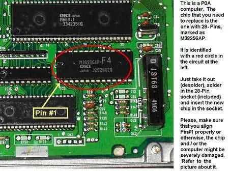
Note: The “xx” after the “M38256AP” is different on every ECU computer. It is the code of the program written inside the chip. The picture below is an example of the Honda Accord’s P0A-A51 (F4). For the P0B ECU, it will be “F5”, for the P14 ECU, it is “C8”, and so on. So before buying a performance chip, open the ECM and check that number to make sure the chip fits your model, since every ECM model can be different.
Every ECU has an identifier code. For example, the Prelude’s P13 has 4 different codes: “A6”, “E6”, “C2”, and “C3”. In this case, the code depends on the ECU’s domestic market. So, A6 and E6 are Japanese (JDM), and the two programs differ. C2 is for the USA ECU (USDM), and C3 is for the UK European ECU (UKDM).
One technique for removing the chip, though it still requires patience, is to solder each pin one by one by adding excess new solder. That way, the solder comes out more easily when using a vacuum desoldering tool.
Never use a soldering iron above 35 watts with these ECMs to avoid destroying circuit copper traces and connections or damaging the chip internally. Always apply soldering flux to the area you’re working on before starting any job on the circuit. It greatly helps, as it cleans and rejuvenates the solder when heated.
After removing the old chip, clean the area with alcohol, remove excess solder with desoldering braid, and then check the whole area for broken traces or potential connection issues before soldering the 28-pin socket in place.