Troubleshooting a Honda P28 Chip Installation
Did you install a performance chip in a Honda P28 ECM and it is not working? Having problems?
This situation is more common than you think, as many people choose to install a chip by themselves, even if they have no experience with electronic parts soldering. But wait, this happens even to professionals, so let’s see what can be done to troubleshoot the problem.
Functions of the Added Parts
The installation consists of adding some parts to the circuit of the ECM and by doing so, sometimes mistakes happen.
The parts added to the circuit are; two capacitors (for filtering electronic noise), a resistor for activation of “external memory mode” of the MCU, the new EPROM chip (inserted into a 28-pin preinstalled socket), a small 20-pin chip (74HC373 latch to address low and high memory pages by multiplexing) and a jumper (J1). The jumper “J1”, enables or disables the new chip. Since it is in series with the “external memory” activation resistor “R1”, when this jumper is installed in the circuit it enables the newly installed chip and disables it when cut. Just like a switch. A switch can be installed instead of “J1” to externally activate or deactivate “power” or “stock” modes.
Basic Troubleshooting Method
NOTE: This article covers not only the Honda P28, but also the Honda P05, P06, USDM P30, P72, P74, P75, and OBD-I PR4 Honda computers family.
We are basing this troubleshooting on simple connections confirmation with a continuity tester or an ohmmeter.
First Step
If your car is not going over 4000 RPMs, it is in “limp mode”, which is a default mode programmed in the ECM to avoid the engine from damaging if something wrong was detected in the system. So the first step is to cut the “J1” jumper. If all goes back to normal, the problem is in the chip. It is either no good or not compatible with the ECM. Many Honda models are similar, but even if they are from the same year, if the trim is different (Civic EX and Civic CX for example) the program in the ECM might be different and a chip not meant for it will activate the “limp mode” and will not go over 4000 RPMs.
If all stays the same and the problem persists after cutting or removing the “J1” jumper, then remove the chip from the socket and try again keeping the “J1” jumper cut. This will rule out any internal short circuit in the EPROM chip. If the problem persists, then go to the next step.
Second Step
The next step is to check the installation for solder bridges among pins or broken copper traces. Do a visual inspection first. If nothing seems to be broken or bridged with solder, then you will need to do a test of the connections pictured in the table below.
The table below shows what connections should have continuity. If any of the points of the table give no continuity, then a line or connection is broken between the two points and if not spotted visually, you may run a wire between both points. Just look for the nearest point that has continuity to each part of the broken connection in the circuit board and solder from there. If this is done, the wire should be kept as short and close to the board as possible. This will prevent the wire from picking up or generating electronic noise.
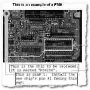
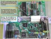
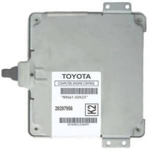
The pictures below before the table, are to help identify the three components the table is based on
Identifying involved components:
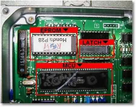
Pin Identification of involved components:
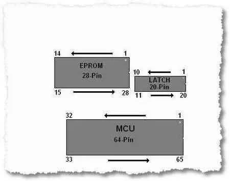
Use your ohmmeter or continuity tester and test each one of the 28 pins in the table below (left column) to each connection identified at the right column. Make also sure that none of the contiguous pins on each one of the three chips referred here have any continuity (example: pin#1 with pin#2, pin#2 with pin#3, and so on for each one of the three chips).
Connections Test Table:
| EPROM Check Points | |
| EPROM Pin# | Connects to: |
| 1 | #20 of Latch |
| 2 | #13 of MCU |
| 3 | #15 of Latch |
| 4 | #12 of Latch |
| 5 | #16 of Latch |
| 6 | #19 of Latch |
| 7 | #9 of Latch |
| 8 | #6 of Latch |
| 9 | #5 of Latch |
| 10 | #2 of Latch |
| 11 | #3 of Latch |
| 12 | #4 of Latch |
| 13 | #7 of Latch |
| 14 | #1 & 10 of Latch |
| 15 | #8 of Latch |
| 16 | #18 of Latch |
| 17 | #17 of Latch |
| 18 | #13 of Latch |
| 19 | #14 of Latch |
| 20 | R54 (left side) |
| 21 | #11 of MCU |
| 22 | #23 of MCU |
| 23 | #12 of MCU |
| 24 | #10 of MCU |
| 25 | #9 of MCU |
| 26 | #14 of MCU |
| 27 | #15 of MCU |
| 28 | #20 of Latch |
All the connections in the table should measure continuity (less than 1 ohm) with an ohmmeter or continuity checker. Any reading over 2 ohms at maximum is an indication of a faulty connection.
The only connection that is left out that table is the following, so please also test this one:
Pin#11 of the HC373, connects to Pin#22 of the MCU
Third and Last Step
If step 1 and step 2 above tests do not reveal the culprit, then the latch 74HC373 chip must be (1) put in reverse or (2) be damaged. If it is damaged, it could be that it came this way or it was damaged by overheating when soldering it or by static electricity. In this case, all will go back to normal as soon as that chip is removed from the circuit.
If the 74HC373 chip is bad, it is a common digital chip and can be ordered from many local or online electronic markets, fortunately. So by removing the 74HC373 from the circuit and keeping the “J1” jumper cut, you will be able to use your ECM in normal mode (stock) while a new latch chip arrives. You may leave the EPROM chip in the socket and the “J1” jumper must be cut meanwhile.
FAQ
Q – Will a chip with incompatible program damage my ECU?
A – No. The ECU will activate the check engine light steadily and go to protection (limp mode) to avoid engine damage. To achieve the purpose of protection, it won’t allow the engine to go over 4000 RPMs and fuel mixture will go very rich to avoid destructive lean conditions.



Nice Site layout for your blog. I am looking forward to reading more from you.
Tom Humes
Thank you Tom. I’m glad you liked it.
Thanks for reading.
I did all that is said here and still having problems, so i conlcude it is the chip i bought from ebay, as cutting j1 makes the car works good.
Hello. If cutting “J1” solves the problem, definitely the problem is the chip. It may be that the chip program is not compatible with your ecu, it may be that the chip architecture is not compatible with your ecu electronics, it may be that the chip electronics are damaged (static electricity or other factors) or it may simply be that the chip is garbage.
Please, before buying chips on eBay, make sure that the seller knows what he or she is selling. Make technical questions. Simple answers like “yes” or “no” to your questions is simply not acceptable. Many chip sellers on eBay don’t know a thing about electronics, programming, mechanics or even driving safety.
Be smart and be a step ahead.
Regards,
Richard
I forgot to mention some history about chips.
Some time ago many forums on the INTERNET that shared technical information about modifying chips for different car models, used to post the modified file along with the original file and all information about it, including algorithms to accurately make the calculations for customizing chips. Then the eBay boom began when forum users, specially “newbies” started to download the modified files (prototypes from forum users)and using them as good and completed, to make and sell chips on eBay. As it should be expected, many chips that were sold this way, failed and some caused damage to engines. When people started to complaint on eBay, the word spread out and Forum administrators started to restrict users because of this behavior and some of the admins even prohibited sharing modified files at all in their forums. Those chips are still on eBay and are now sold for cheap in an attempt to sold the greatest quantity possible without caring about customers.
To prevent from being banned or avoided by buyers, they started putting bogus information on auctions like “We have been chipping ecus since xx year, and we know what we are doing”. But facts go further than words and people realized otherwise, but only after having spent their money in such a garbage.
The real problem on eBay are buyers. People leave feedback before even trying the product. Only a few were brave enough to test first and then give feedback. That is why there are many feedbacks that state “nice looking”, or “fast shipping” and many more that doesn’t speak for the product, but for the service.
A few also tested the chip and felt something, but didn’t realized that it was the “placebo” effect, fooling them into thinking that it is a good product, even when the car ran the same as before. Yes, many stock chips were and still are being sold on eBay as performance chips. This placebo effect was also caused by the infamous IAT resistor in most cases. This happens often to people that have not tried any chip before and didn’t know how a real good chip should feel.
About the IAT resistor, many buyers had no other choice, as these resistors and fake modules, are offered to every car, even new ones, while real chips are only available to few models and are limited in Manufacture Year, since most car computers from 1996 and up (OBD-II) don’t use those chips in their circuits. A sure sell was obvious.
Other chip buyers, were not fortunate enough and their cars didn’t even start. Some started, but blew their engines when test driving because of a hard knocking in the pistons caused by a too advanced ignition timing and a too lean AFR mixture induced by the chip. Of course, the seller didn’t know about this, so If you would ask him, they would have said otherwise.
About Honda, many sellers say they sell “Mugen”, or “Spoon”, “JUN”, etc., but if you call every one of the mentioned Companies, they either say that they didn’t make those chips or that they don’t make chips for those cars or applications. Some of those Companies complained to eBay and eBay forced sellers to change the name of their products as they were violating the VeRo rules by copying a trade mark. That was the birth of M-Gen, instead of Mugen for example. After some years, I guess that those Companies got tired of trying to eradicate those trade mark infringements because once in a while, you will see their trade names again on eBay for chips.
I think part of this began for Honda chips when someone published a list of chip files that were sold by a Malaysian guy named Richard Wong. They advertise chips that will tune your car like “Mugen” or “Spoon” do, but those were not from such Companies, but an adaptation of some “supposed” read codes from them. Whatever happened, those Wong’s chip files were intercepted by today’s eBay sellers (with exception of a few of them, like Auto-Motivo) and are the same chips that have been sold as of today, though each one claim different and add supposed attributes. The only attributes that they can really add are VTEC change over and revlimiter in many cases, thanks to free softwares that have been freely distributed by a few talented people that were kind enough to let everyone have it. Still, today exist many parameters of chips’ program codes that are still not understood in full or at all, either because lack of knowledge or special tools, or simply because of lack of interest, so even those free softwares are not the complete solution.
Any question, please post in the “comment” area below.
Richard
wat is yo fb name?
Hola, Me gusta mucho tu sitio, ?sigue haciendolo mejor!
I am amazed. I don’t think I’ve met anyone who knows as much about this as you do. You should make a career of it, seriously, impressive site.
Many thanks for the site, it truly is loaded with a lot of handy information. This helped me a lot.
Can i ask you about this?
Sure, go ahead.
This is a really great site!A lot of helpful info and handy tips, bless you =)
Wow! This might be one of the most helpful things on the matter I’ve ever come across. Thanks for your hard work.
I have discovered a lot of useful information on your site particularly this page. Thanks for posting.
So my ecu is square. It’s has a chip in it that has 2 step on it with the j12 resistor cut. If I cut the j1 resistor should I solder the j12 back on or can I leave it how it is and just cut the j1 resistor?
Hello Jason.
It should go back to stock just by cutting j1, but since I am not sure why they cut j12, if cutting j1 does not do the trick, you will probably need to join j12 too as you suggested.
Once you cut j1, the microcontroller should switch back to the internal (stock) programming (maps) and should ignore the installed chip, no matter that it is still in circuit.
To make sure, cut j1 and test. If having problems, disconnect the ECM, join j12 and test again.
Kind regards,
Richard
Is there a way to tell if the ecu is vtec or non vtec? My vtec doesn’t engage and I’m thinking it’s the 2 step maybe. But i will try what you suggested. My car is a 93 Honda Accord ex with a f20b motor swap and it jerks when it’s fully warmed up like it’s dying for fuel. I just replaced the fuel filter so i don’t know if the ecu is just not tuned right or what I’m not really michanically inclined so sorry if I confusing you.
Thanks, Jason
The most effective way is looking at its programming, but one needs to know the programming to know if it is activated anyway. For example, if I see the programming of a chip for P13, P0A, P0B, P28, P30 and P06 among some others, I can tell.
Another way would be to check if the VTEC solenoid activation transistors are present, but for this, you need to know the circuit too, so summarizing, there is no easy way to tell from an unknown setup.
What ECM number are you using (“37820-Pxx-xxx”)?
Anyway, while you reply, for now, the best way would be by cutting/joining the jumpers.
It’s 02D011F0 – 1500 I’m about to test it with the j1 resistor cut. If you have Facebook message me my name is jason ray on there it’s gonna be a blue picture of a little boy posing. Maybe I can send you pictures
The part number should start with “37820” as all Honda engine ECMs. About connecting on Facebook, I am sorry for not being available for now. I have some work backlog that I need to put up to date. Anyway, my facebook page is facebook.com/rav4repair
Regards,
Richard
This is a really great site!So much helpful information and handy suggestions, thanks a lot =)
Hello awesome info what .bin file would work on a p27 ecu new zealand new ? I also have like a massive hesitation withthe car and code 11 which is not listed anywhere got me bit stump even with j1 cut still issues .any help will be appretiated
Hello Clint. The best way would be to have the original file of the P27 and start from there. If Using a P28 file, if it is a real P28 file, because I have seen P30 and P72 files used and sold for the P28 ECUs, it may create errors if there are changes in memory locations between the two.
Unfortunately, I have never had or seen a P27 ECU or file. The ones I have worked with are the US market files, like the P05, P06, PM6, PW0, P28, some P30s, and so on. That being said, I have no idea which other available programming (file) would be compatible with the P27.
Also, if you cut or removed J1 because you had a chip installed, do not rely on “J1” alone. Take out the EPROM chip too in case there is a short or anything wrong with the installation in that area (hopefully it is in a socket). The J1 jumper disables the external EPROM and switched the microcontroller to the internal EPROM, but electrical problems, like a bad chip, will make the problem persist.
Best ecu chipping problem info online. Very easy to follow your diagnostic steps. I have a p06 chipped and also vtec hardware installed. It was running right on a tune my buddy gave to me with it. After trying to alter the tune it got stuck in limp mode. I followed your steps and my conclusion is that the latch chip must have gotten dmged by static when pulling or installing eeprom chip. Thank you for your indepth knowledge and hard work on this site.
Hello Richard,
I am having a problem that I can not seem to solve. This site has the most in depth info that I have been able to find. I even read all the comments, I have done a lot of research trying to figure my issue out. Good job keeping up with comments too.
Basically, I have a chipped p28 and had the chip programmed with Crome first, the Honda Tuning Suite now, hoping that maybe it was the program that was causing the issue, but it didn’t change anything. Basically my cn2 port doesn’t seem to be sending out any data. I am wanting to set up a digital dash with a Samsung tablet that I have. First I tried Hondash and app that displays data from the sensors that communicates thru a bluetooth module that they sell and connects to the data link connector that sits up behind the radio/under the dash. Thier bluetooth module communicates in half duplex mode, which is slower but easier because it connects to the data link connector. Couldn’t get it to work, so that’s when I switched programs. The creator of Hondash, I spoke to several times trying to get it figured, says that his module should have worked with Crome no problem, but for HTS I need an internal bluetooth module, so 3 of those later, first two were junk, I’m still having issues. I can pair the module and my phone and tablet no problem. But the app will say “bluetooth connected” and the next line will say “ECU not responding”. I’ve been beating my head against the wall trying to find any info that’ll tell me how to troubleshoot it, I’ve tried asking facebook groups, going on forums, you name it. I come up empty everytime. Everyone I ask for help basically tells me the instructions for setting everything up to begin with. Which I guess I get, I’m sure there is a lot of newbies that just forget something. But I’ve been over everything several times, tried different programs, different settings in the programs, j12 is cut to enable full duplex communication…. so frustrated. I’ve asked people who are suppose to be the experts on this sort of thing how to troubleshoot the components on the circuit board and never hear back. I know the aluminum capacitors you need a special tester to test them while they are on the board. But maybe one of the yellow ones or the disk ones went bad, I duno.
Help me Obi Wan Kenobi, your my only hope.
James
Hello, I have this problem with a p28 ECU, the weird thing is that using the OSTRICH 2.0 I was able to work on the car and complete the tune perfectly, then when I burn the chips and I put it on the ECU is going to limp mode, I cut the jumper J1 and works fine again, my question is, should I change between 32kb and 64kb chip region? or what else to do, I never had a problem like that with the chips that I used and I don’t know that else to do. Is a p28 but I used a base map for a P72 because the car is a B18 with vtec. I hope someone can help me.
I have the same problem as Joshua Cisneros, didnyou ever fixed it?
Hello André. If you take a look at the binary files of the P28 and the P72 programs and compare them, you will notice that the software is completely different and addresses different memory locations too. So the fact that cutting the jumper “J1” makes the car work fine, it means that the issue is the code, not the chip or the installation.
The microcontrollers used in those models are similar, so even with the code being compatible at assembly levels, I guess that memory locations addressed in one ECU (P28) is different from the other ECU (P72). It is maybe just a block of code somewhere in the whole program but I cannot exactly tell where the issue is because when I used to do Honda chipping, I used to use the code for the same ECU and not interchange codes between them. I mean, it is possible as it has been done many times, especially porting the P72 program (Integra, dual butterflies throttle) to a P28 ECU (Civic, no extra butterflies throttle) but it requires modifications.
About what Cisneros suggested of using a 27C512 chip instead of a 27C256 chip, as long as the access time of the EPROM used is similar or faster than the original one (usually 200nS), then you are good to go with either. However, if you use a 27C512, since it is twice the memory size of the factory 27C256 EPROM, you should duplicate the code in both pages of memory. In that case, whether the lower 256Kbits page is called by the MCU, or the higher 256 Kbits page, the code will be exactly the same and it will work flawlessly as one. Since the highest address bit pin is mostly tied to +5v in the ECU, it will almost always use the higher 256 Kbit page but to be safe, it is best to duplicate the program and use both pages.