IAT Resistor Mods vs Performance Modules vs Real Chips
What are those infamous IAT resistor mods and performance modules and how do they compare with real EPROM performance chips? Need a guide to try it out by your self? Find out here…
Some background
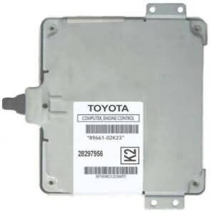
The ECM is able to do such a gigantic job by executing a software created for that purpose. This software is called and executed every time you turn the key to start your car. The software is specific for each engine and each ECM and allows to easily control the engine in a way that previous mechanical (fixed) systems could not. Modern cars no longer use carburetors. Instead, they use what we know as Electronic Fuel Injection or EFI for short. This EFI system is controlled by an onboard computer called the ECM or Engine Control Module. The EFI system replaces the carburetor functions entirely. It does the job by sensing environment variables such as atmospheric pressure, air temperature, ignition advance angle, coolant temperature, altitude, air density and some other variables that allow such a system to precisely determine the exact amount of fuel needed to be injected to keep the engine running smoothly and in optimum conditions.
The EFI software is composed of the (1) executable software which does the calculations and movement of data and the calibrations part, which stores the tables of parameters for running the specific engine. These parameters are the ones that mark the limits and operation ranges, like fuel injection amount, calculated in injector opening time in milliseconds, ignition advance, calculated in degrees, maximum speed the engine is allowed to rotate in RPMs, maximum allowed vehicle velocity in MPH or KM/h, and many other things. These are precisely the parameter that chip tuners modify to accommodate new engine hardware, like cold air intake, different cams, boosted induction, new rim size and so on, or simply to optimize the existing hardware, like lowering engine temperature by activating the engine fans at lower temperature, modifying ignition timing to make the most out of premium fuel, etc.
The modification of the engine parameters is done by modifying values in the EPROM memory that contains the engine stock program. At least that is the most effective way. But there are also the “piggybacks”. These piggyback alter such parameters indirectly. They instead, intercept the signals coming out of the different engine sensors and modify such signals before sending them back to the ECM. This way, they “coerce” the ECM on changing the way it responds to the modified sensor signal. If for example, you modify the signal coming from the vehicle speed sensor, you can change the reference used by the ECM, in a way that it “sees” the sensed speed as being lower than it really is, allowing for higher vehicle speeds as the ECM moves up the speed limiter.
In a similar fashion, people started trying to modify some signals in an attempt to “fool” the ECM into producing more power from the engine by injecting more fuel. The most used is the “IAT resistor”. This is, a resistor connected in some way to Intake Air Temperature sensor (IAT), to “fool” the ECM into “thinking” that incoming air is cold, hoping that the ECM will inject more fuel to compensate for the “colder” air. ECMs are programmed to compensate in some way when the air is colder, as colder air carries more oxygen for being denser. More oxygen may induce an unbalance in the air/fuel ratio, so it is balanced again by increasing the fuel delivery.
The thing is that this does not necessarily happens that way, or at least not with most ECMs. ECMs are smarter each time and many ECMs take into account not only the incoming air to start doing changes in fuel delivery but take also into account other readings to do so. That is why many “resistor mods” will not have any effect, but still, scammers sell it by fooling people and offering horsepower gains as high as +100hp. The fact that it does not work is why many other scammers decided to “try luck” tampering with the oxygen sensors instead. You know, there was a time some years back that Google reported that “+20hp” was the automotive term most searched for. But then, they moved to higher numbers.
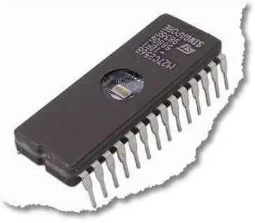
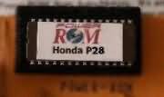
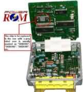
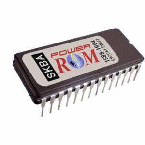
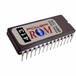
This is an example of a “real chip” or EPROM chip used to store the software of the ECM:
Automotive Products, Services, and Articles
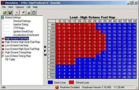
Example of changes made in the EPROM chip by modifying the parameter tables, called “maps”:
Automotive Products, Services, and Articles
IAT Modification scams
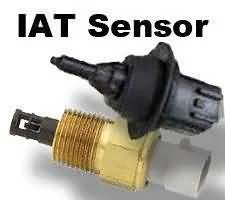
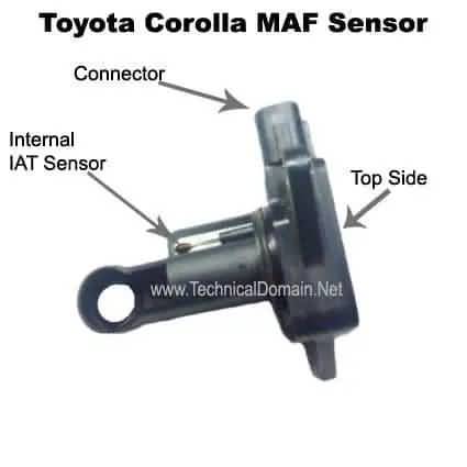
These are some examples of external IAT sensors, which are mounted separately from the MAF sensor.
Automotive Products, Services and Articles
Automotive Products, Services and Articles
The main focus of this article is to allow you to do your own modification to the IAT in case you are curious and do not end up giving away any money to those scam artists.
The modification was at first a simple resistor with a couple of wires for you to install it in the IAT sensor with a blurry diagram. Then they started putting the resistors in fancy boxes to look like an elaborated product, but still, you would see only two wires coming out of it. Some scammers used a dummy connection and added two wires more, making it four wires. Finally, when the scammers knew that many people found out about the “resistor in a box” scam and when people started looking inside the fancy boxes to find just a single resistor inside, they started to put some random circuit inside and the two wires were soldered to anywhere in the circuit that measured the desired resistance. It was hilarious! Not only the $0.25 resistor with two wires in a box, or the elaborated that the box was or putting a random circuit to make it look like it is complex equipment, or how many dummy wires they added but the fact that people paid for it! Believing their claims of “+50hp” or more! From $40 to $100 for that scam! And if you opened the box to see if it is a resistor, they tell you that you voided the warranty even when they scammed you and it was a resistor in a box! LOL.
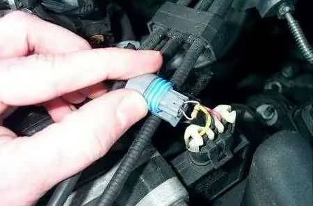
Automotive Products, Services and Articles
Do It Yourself
Well, let’s go back to the experiment. The IAT sensor is nothing more than a thermistor. That is; a resistance that changes its ohmic value as temperature changes. The thermistor used in the IAT has a negative coefficient, which means that the higher the temperature, the lower the resistance in ohms.
That being said, as you may deduct so far, if you want the computer to “think” that air is colder than it really is, then a reading of a higher resistance from the IAT is what we are looking for. Many IATs go as low as 200 Ohms when hot around 100 degrees Fahrenheit and go up to 5000 – 7000 ohms at low temperatures like 30-50 degrees Feranheith. This is only an approximation, as all IAT thermistors have s slight different response, but always with a negative coefficient.
So you will need to know the response of the IAT sensor of your car, which is how many degrees directly convert to how much resistance and what temperature in degrees you want to move up the response range of the ECM.
The first one, the IAT response, while it could be in the documentation of the sensor manufacturer or the car manufacturer, the easiest way to know is by using a low-temperature source like ice or a cooling no-residue spray and directly measure the temperature and the resistance. The second one, the range to move up the response of the ECM is completely up to you for experimentation.
Example: You want to make the ECM “think” that no matter the fluctuation, the incoming air temperature is always 50 degrees colder. So if the IAT resistance is equivalent to 80 degrees, the ECM will “see” it as 30 degrees. If it goes up to 90 degrees, the ECM will “see” it as 40 degrees. That way, if the ECM is programmed to compensate only by air temperature, you will have more fuel injected along the whole range of temperatures.
Now, you will need the resistance equivalent value of the IAT sensor for those 50 degrees that you want to subtract so you can pick a resistor of approximate value and put it in series with the IAT sensor. The easiest way this can be achieved is by putting water in a cup with a thermometer in it and the IAT sensor touching the water. Add ice until the thermometer goes down to 50 degrees and then measure the resistance of the IAT. Let’s say it measures 4600 ohms, then you may use a commonly available 4700 ohms (4.7k) resistor in series with the IAT.
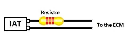
IAT Series resistor
The above procedure is easy if the IAT is separate from the MAF. Otherwise, you will need to use a cooling spray as a source of low temperature for getting the needed equivalent to 50 degrees resistance value. If using the spray, make sure it leaves no residue or you may damage the MAF sensor. If using the water cup on a separated IAT, make sure you dry it completely before installing it back in the car.
Once you get the value and find a suitable resistor, just connect it or make a harness to hook it in series with the IAT. That way, every change that the IAT does in resistance due to temperature fluctuation, it will be added to the series resistor you picked. After this, you will need to do tests in a dynamometer or some sort of setup to know if it really works. Don’t just use your “feeling of it” or any qualitative observation as it could be subjective. You need quantitative measurements here. If nothing is enhanced about performance or even economy, just think that you did not have to buy the “resistor in a box” scam to find out.
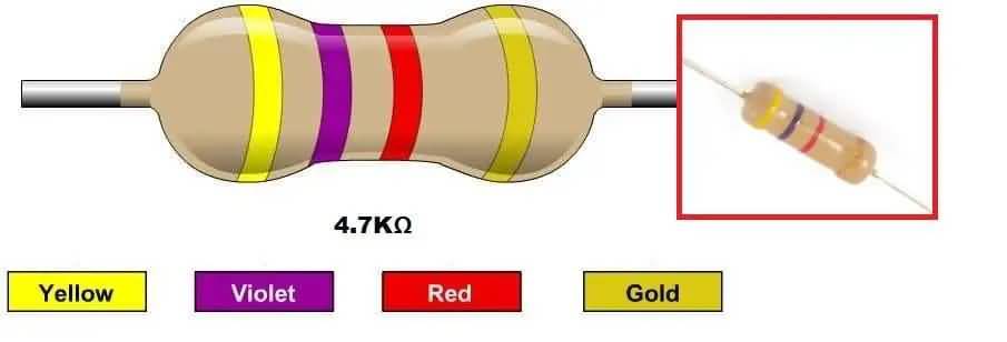
A typical resistance value widely used is 4.7k (4700 ohms), but if you wish to be near to the exact value of your car model, you will need to do the experiment detailed above.
Below is an example of a 4700-ohm resistor. Color bands must be YELLOW-VIOLET-RED. The fourth ring can be GOLD for 5% tolerance.
On the other hand, if this does not work, it means that your car’s ECM does not use only the IAT sensor for increasing fuel injection. You can be sure that it does it in some way, just not with the IAT sensor alone. Have you ever wonder why your car moves better at nights, especially on cold nights? Precisely because the ECM detects more oxygen contents based on some parameters and injects more fuel. Modern cars base such calculation on temperatures, but also on air density by measuring the actual mass of the incoming air. That is what the MAF sensor does. The thing is that some older cars used to use an Air Flow Meter (AFM) instead of a MAF (Mass Air Flow sensor). Also, some Honda cars do not use air flow or air mass at all, but engine load by using a MAP sensor or “Manifold Absolute Pressure” sensor. The difference obviously is that while the AFM senses air flow, no matter the density of the air and the MAP senses engine load by vacuum or negative pressure, none of those two check the air density. The MAF senses the mass of the air, which tells the ECM how much dense is the incoming air. Measuring the mass of the air is an indirect way of measuring oxygen contents in that air. The denser the air (more mass), the more the oxygen contents should be. So that nice accelerations at cold nights or cold weather, in part are because of the low temperature and we can take care of that by fooling the IAT sensor. But the other reason is the detected air mass and there is nothing we can do about it unless you inject nitrous oxide and that, is another story.
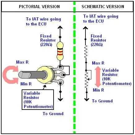
Variable Resistor
You may also replace the IAT with a variable setup in case you wish to adjust values on the fly:
Automotive Products, Services, and Articles
Other Factors
There are some other factors to take into account if the resistor does not work.
- Too much fuel: It is true that more fuel injected may produce more power, but only to some extent. If the fuel/air mixture gets too rich, you start to lose power instead of gaining it. Make sure that your modification(s) does not cause excessive fuel injection.
- Engine temperature: Remember that you are trying to “fool” the ECM into “thinking” that temperature is colder, but it really is not. So if you live in a hot area, if the engine temperature goes over a certain level, it may cause the ECM to lower the ignition timing to prevent engine damage. Lowering ignition timing has an immediate power loss side effect.
- Altitude: Altitude matters! The higher the altitude over the sea level, the lower the oxygen. Enough oxygen is key for producing power in internal combustion engines. More than 1000 feet above sea level will produce a palpable lack of power. The closest to sea level altitude, the more the oxygen contents of the air.
Example of scams being sold all around
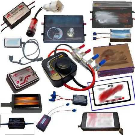
Automotive Products, Services and Articles

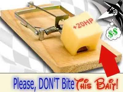



I often see questions and search engines results, stating “are performance chip just resistors?”. In this post you will find out that the answer is -no-. Real sellers sell real chips and then, there are the other ones.
Sometimes, “Performance Chips” is just a nice name that some people put on an item for successfully selling it.
Imagine someone trying to sell a “racing resistor”.
A lot of people get disappointed when they pay some amount of money and are excited when it finally arrives to their mail box, only to find out that they have been “ripped off” with a nice box with a resistor inside.
I personally bought one once from an online store and it didn’t even was enclosed in a box. It was a simple resistor in an envelope, with a very hard to read black and white blurred instructions sheet… well, you can imagine what an unpleasant feeling it was and how angry I became with my self…
I personally run an eBay store and offer real chips. At the moment we have only several chips and services, but we are expanding step by step. You may ask any question you have about any of the items or services on the store.
Richard
http://www.racingchips.net
Hey thanks for the info! You saved me some money. I was about to buy one of those “modules” when I found your article.
Cheers
Frankie
I have also seen questions like: “is it safe to put an ait sensor module in your car”
The answer is yes. Trying it won’t hurt your ecu or engine. There is no too low or too high of a resistance value that will hurt any of both. Just avoid shorting the connector with other sources like ground or + battery terminal.
hello i bought a “performance modules” it is cost me 120 dollars and a time i break and only had a f**k it resistor of 1 cent dont buy that peace of s**t much better go to radio sack and buy a 5 resistor by a dollar and its work the same ok bye
Yes. That is the result that is often obtained from those “modules”. Just take a look inside that box and you will see the sophisticated circuit of just one resistor…
Thanks for the info, works great!
Love the advice. Thank you.
Thank you for sharing. I came to this site to read how things really are
We will post soon a follow up of this info, based on requests made by visitors. Just use the search at the top of this page to check if it is available yet.
(search for IAT, etc.)
Thanks to you all for reading.
Richard
Man I did it myself and didnt worked no matter what value in ohms i used. These guys at ebay selling resistor for a lot of bucks r some clowns. poor them who buy from them.
I am glad this information is helping people to not get into a scam.
By the way, the additional information was already published at:
https://qcwo.com/technicaldomain/?p=245
has anyone tried a resistor in a Honda civic
2007 vw caddy tdı resistor what ohm ???
WHAT RESİSTOR OHM VW CADDY TDI OHM???
Hello Mehmet. Resistance of most VW’s IAT run considerably lower then other makes. It is as follows:
86F(30C) – 1.5k – 2K
104F(40C) – 1K – 1.5K
122F(50C) – .8K – 1K
140F(60C) – .5K – .7K
158F(70C) – .3K – .5K
176F (80C) – .27K – .37K
194F (90C) – .22K – .27K
All values are in K-ohms (x1000 ohms), so for example, 1.5K = 1500 ohms and .27K = 270 ohms.
Good luck.
Hello J.
I hope someone that have tested it on a Civic can post his or her experience here. Myself, i haven’t tried on Civic, as I use chips for Civic (if it’s OBD-I), but tested on Mazda Protege, Hyundai Scoop and Accent, GM Cavalier and Ford Taurus, among some others and haven’t noticed anything.
But of course, as i said, it will be nice if others post their experience.
HELLO IM VW CADDY TDI .FUEL TEMPETURE 2 PIN MODIFIYE RESISTOR WHAT
OHM ???
Mehmet, you may look at the information in the table for VW above. If I was doing it for a VW, I would use 2.2K-Ohms for simulating colder than 86F(30C). The color code would be -red,red,red,gold.
I was told you can connect a 20 k adjustable resistor pot in parallel to the original car IAT to retard the timing is it true?
I am running hho(hydrogen)and I want to retard the timing.
Hello Nikolas. If your car is one of the models that ONLY take the IAT sensor input to make changes, AND, those changes made are in both the fuel and timing areas, then yes, an adjustable or any other resistor in PARALLEL with the IAT (with the IAT in the circuit, NOT disconnected), will make the resistance value to go down, making the ECU “think” that the incoming air is hotter, lowering the fuel being injected and retarding ignition (in fact, not retarding, but advancing less than normal) in an attempt to avoid detonations that would happen if the temperature would be truly hot.
You will also feel a loss in power due to that, so if you feel the loss, then the resistor is doing the job.
The fact that it is an adjustable resistor (potentiometer or just “pot”), you can play with it to bring it to different resistance values. The lower the total resistance in the circuit, the less advance it should apply.
As for the potentiometer, I think that using 20K for that purpose is in the right track, since that value would cover 99.9% of the values presented in an IAT sensor.
As a final comment, as you mentioned that are using HHO, please note that as noted above, the fuel injected will also be less. I mention that just in case you are counting on the actual fuel supply and haven’t consider a variation (injection).
Best regards and Good luck.
what about those modules connectting to the obd port? cuz im looking at one right now well actually still because you went into great detail of replacing your ecu or (not) gettin a iat resistor online but wat about the obd port mods?
Well, if you refer to modules like the one offered by Superchips, for example (Micro Tuner), they do work as they are a completely different approach. Instead of being a plain resistor, they are complete hand-held micro computers, each one programmed for specific cars.
Those modules are a real solution for performance, but are a bit expensive ($200 – $500)
They connect to the ecu through the OBD-II (diagnostic) port and reprogram (flash) the internal memory, inserting a performance program. It will be the same as installing a performance chip in your ecu, with the exception that such modules often offer a menu with different performance levels to choose from.
It is done through the diagnostic port because most 1996 and newer vehicles did not come with a replaceable chip on their circuits. Instead, it is re-written this way.
With those modules, still assuming we are talking about the same modules, performance varies from manufacturer to manufacturer. One good thing is that it stores in memory the original contents of your ecu, in case you wish to go back to stock mode. You may go from performance to stock and back as many times you wish, as long as it is used in your vehicle.
Once you connect it to your vehicle and perform the first programming, the VIN number or any other code is automatically stored on the device for it to identify your vehicle.
If the modules I described are not the ones you refer to, just reply to this thread with details so I can help you better.
Cheers,
Rick
simple things i have a 1.4 honda civic 98 with 75HP’s from its mother i did those modifications :
i have a cold air intake + 6-10HP
final exaust system + 3-7HP
iridium sparks +1-2 HP
IAT sensore RESISTOR makes the cold air intake’s gain +2-4 HP to the excisting values
2 neodmium magnets + 2-4 HP’s(ionizers)
now my car is 97 HP’s tested ! i don’t need to reprogramm my ECU because i gained 22 HP’s without touching it.!!!
one more thing DO you know that the Catalysts in all cars REDUSES the Horsepower from 6-10 HP’s ??? if u have the money go buy aftermarket ‘racing’ and you’ll see the diffirence
Thanks
Well, I’m glad you obtained all that extra power without even reprogramming the ecu. It would be nice to look at the Dyno charts before and after the mods.
I guess you have the charts, since you stated that gains were tested. Also, are the mentioned gains in BHP (engine) or WHP (wheels)? Not contradicting you, I just would love to know the details. That way, more people can take advantage of the tricks.
As you mentioned, your car is 1.4L, so I guess it is a Diesel model. Since this website is mainly oriented to gasoline models, I can not comment on this and will be open for discussion for Diesel savvy people.
Thank you very much for your comments.
Best regards,
Richard
No it isn’t diesel is gazoline and is only 1.4 lt . this model is from germany and i live in greece i don’t have the dyno test but the 97HPs (96,73) exactly are true i tested on my friends dynamometer and is WHP not BHP.
i can only tell u this from stop 600 meters race with a VW polo 2000 1.4lt with 101HPs from its mother- i am 2 cars ahead and i tested at least 3-4 times before the modifications i was 2 cars back.
as for the details
i will inform you soon when i make the details 🙂 thanx
Nice! About the cold air intake, as you may know by now, the cooler, the best. If using a metal runner on the ram air intake, it will work even better if you insulate it with a heat resistant material like that used on air conditioners that is made of foil and glass fiber. The less heat the runner absorbs from the engine, the cooler the air will enter the engine and since cooler air has more oxygen concentration, will turn in even more power!
I know, not too aesthetic as a chrome metal runner, but will perform better.
Will look forward for the info. Thanks for sharing it!
Best regards,
Richard
So then: These ‘2cent’ resistors will(not:-[) work on a Diesel?
Not aware that similar criteria applied to CompIgn fuelling… Live & Learn :<)
Hi all,
I have bought a “Performance Chip” (it is a box with 2 wires coming out – look like there is only a resistor inside) on EBAY with the price of $24.99 and it is wonderful. My car is running smoother and faster, look like it is gaining horse power too. I really love it. Here is the one that I bought:
http://cgi.ebay.com/ebaymotors/ws/eBayISAPI.dll?ViewItem&item=320363004525
If you don’t know how to connect, ask the seller (send him an email and he will answer within 48 hours)
The only thing I has changed from instruction that instead using the clip to connect the wires, I sliced out the wires and connecting them to make sure that they have a good contacts with each other. PERFECT.
Hello Friendly Guy. It is good that you bring this to discussion here. The product you describe is exactly that, a simple resistor inside a box.
Sellers are just learning about that scam and repeating it again and again. As long as there are people buying their lies, they will continue doing this.
Could you imagine? Not enough with the extra horsepower scam, now they add that it will save fuel!!!. How in the world can it save fuel if it is injecting more fuel in the case that it would work???
I am an Electronics / Automotive technician and I posted here the truth about those resistors scams so people have the opportunity to make the right choice between the reality and being scammed.
No offense, and if you feel it works, nice for you, but sure you haven’t tried a real chip or a real tuning.
From the same seller, here are some people that think different than you do, just to list a few. This was taken from his feedback history and the common answer from him to all those buyers is “you did an incorrect install”
It is part the buyer and part the people that keep sponsoring such actions by buying his fake products. It make it seems like performance doesn’t matter any more, but how much they lie and how good the fake product looks, which will boost the placebo effect.
Cheers,
Richard
FEEDBACK: Item never left your store.Confirmed by USPS.Lied about shipping it 2 times.Poor
ITEM: BEST PERFORMANCE CHIP GAS SVR DODGE RAM 1500 2002 4.7L
FEEDBACK: Item simply not peformaned as advertised, Other feedback implies mine is not odd
ITEM: PERFORMANCE CHIP PONTIAC FIREBIRD/TORRENT 1995-2009
FEEDBACK: got no change in hp,worked with cus. ser. & still no change.inst. rite 2!
ITEM: #1 PERFORMANCE CHIP JEEP WRANGLER 2005, 2006, 2007
FEEDBACK: e mailed sellerto ask for wiring digram no response tryed three times.
ITEM: 2N1 PERFORMANCE CHIP GAS SVR DODGE RAM 1500 4X4 1997
FEEDBACK: the company knows the device may not work on all vehicles as advertised. bummer
ITEM: 2N1 PERFORMANCE CHIP SCION XA 2004-2006 FUEL SAVER
FEEDBACK: no mpg +, slight performance +,21 days, engine missing,stalling,device removed
ITEM: PERFORMANCE CHIP 3 PONTIAC VIBE/G6/G8/G5/GTO 2002-2009
FEEDBACK: never got my item ,seller woul not responds false tracking number
ITEM: REAL PERFORMANCE CHIP CHEVROLET BLAZER 1992-2005
FEEDBACK: It did’t work in my car I still have it instald and I still hevent seen a change
ITEM: REAL PERFORMANCE CHIP MITSUBISHI MIRAGE 1990-2002 1999
FEEDBACK: fast shipping/answered questions/product does not work for our car/can return
Follow-up – beware of this seller/false nonpayment strikes if not 100% positive feedback!!!!
ITEM: BEST PERFORMANCE CHIP FORD FIVE HUNDRED 05-09 SAVE GAS
FEEDBACK: fast shipping just havent notice any power gain yet maybe to early????
ITEM: BEST PERFORMANCE CHIP CHEVROLET IMPALA 95-09 FUEL SAVER
FEEDBACK: Doesnt do what they claim, even after I hooked it up right
ITEM: BEST PERFORMANCE CHIP CHEVY SILVERADO 1500 Z71 2006
FEEDBACK: doesn’t do anything special
ITEM: PERFORMANCE CHIP PONTIAC GRAND AM 1990-2005 SAVE GAS
FEEDBACK: The delivery was good and quick, but the installations manual was not good.
ITEM: BEST PERFORMANCE CHIP MAZDA PROTEGE 1990-2003 SAVE GAS
FEEDBACK: COMPLETE LACK OF INSTALL HELP! ONLY GOT RUNAROUND. LISTING FULL OF LIES!!!
Follow-up – aviod this seller. car NOT modified. seller makes false claims about no paymnt
ITEM: PERFORMANCE CHIP HONDA CIVIC 1989 2009 BEST
FEEDBACK: Chip is a ripoff there is nothing in the box couln’t get to work so i checked
ITEM: #1 PERFORMANCE CHIP FORD EXPLORER 1991-2009 2004 2003
FEEDBACK: did’nt work on my other truck, Wnot waste the time installing it on this one
ITEM: REAL PERFORMANCE CHIP CHEVY SILVERADO 1500 4X4 2004
FEEDBACK: Opened it up, 2 wires connected to a resistor, 25¢ item for $25, total crap
ITEM: REAL PERFORMANCE CHIP FORD ESCAPE 2001-2009 GAS SAVER
FEEDBACK: SHENANIGANS – a secret, dishonest activity or maneuvering
ITEM: #1 PERFORMANCE CHIP DODGE DAKOTA 1990-2009 FUEL SAVER
FEEDBACK: tried all the suggestions cannot tell any difference with or without it!
ITEM: #1 PERFORMANCE CHIP DODGE DURANGO 2006 GAS SAVER
FEEDBACK: fast shipping, but what I paid for was a product that just simply did not work
ITEM: REAL PERFORMANCE CHIP LINCOLN NAVIGATOR 1998-2009 2005
FEEDBACK: no power or mpg gain at all
ITEM: #1 PERFORMANCE CHIP TOYOTA TACOMA 2000 FUEL SAVER
FEEDBACK: I have not noticed anything after putting this chip on my car.
ITEM: 2N1 PERFORMANCE CHIP & GAS SVR FORD MUSTANG 2004 4.6L
FEEDBACK: I have had no real hp gains or noticed any help for my fuel economy?
ITEM: DIESEL CHIP TUNER 1999 DODGE RAM 2500 5.9L CUMMINS
FEEDBACK: item sucks. had for two weeks and still nothing. garbage!!!!!!!!!!!!!!!!!!!!!!!!
ITEM: REAL PERFORMANCE CHIP & GAS SAVER FORD F150 4X4 1996
FEEDBACK: it did nothing they said it would do, no horsepower gains and no mpg increase
ITEM: REAL PERFORMANCE CHIP JEEP WRANGLER 1995 2006 GAS SAVER
FEEDBACK: this gas saver is a joke! its only a wire in a plastic box! you get what you pai
ITEM: REAL PERFORMANCE CHIP TOYOTA CELICA 2001 FUEL SAVER
FEEDBACK: didnt really make a diffrence
ITEM: #1 PERFORMANCE CHIP ACURA TL 1994-2008 GAS SAVER
FEEDBACK: Fraudulent product; No Difference on my truck
ITEM: #1 PERFORMANCE CHIP CHEVY SILVERADO 2007 FUEL SAVER
FEEDBACK: installed..no change, just a couple of wires..shipped fast, just no performance.
ITEM: 2IN1 PERFORMANCE CHIP GMC SIERRA 2006 2007 GAS SAVER
FEEDBACK: THIS ITEM WAS A FRAUD… NOT AT ALL AS DESCRIBED FFFFFFF- – – – – – – – – – – –
ITEM: BEST PERFORMANCE CHIP FORD CROWN VICTORIA 94-2009
FEEDBACK: THIS ITEM IS A BOX FILLED WITH AIR ,WITH 2 WIRES ATTACHED–JUST PLAIN JUNK
ITEM: A+ PERFORMANCE CHIP CADILLAC XLR 2004-2009
FEEDBACK: All hooked up, correct ! dont feel any performance gains as yet, we will see…
ITEM: REAL PERFORMANCE CHIP JEEP WRANGLER 1990-2009 GAS SAVER
FEEDBACK: Took seller 4 weeks to refund my money so i can revise my feedback…
ITEM: BEST PERFORMANCE CHIP CADILLAC ESCALADE 2007 GAS SAVER
FEEDBACK: Biggest ebay scam ever. Open it up and look inside people!
ITEM: REAL PERFORMANCE CHIP TOYOTA CELICA 2001 FUEL SAVER
Hi Admin,
I have an Lexus 2003 ES300 and it was a little weak before when trying to accelerate from a stop or in motion. The mileage on my car before was about 17mpg in the city and around 30 mpg in the highway. Since I would like my car to be a little faster and I saw the seller has a lot of good feedback (almost 100% at the time I bought the device 2 months ago) so I would like to give my car a try. It works, however, the mileage is now look like fixed at 20-22 mpg even in the city or highway and I have not been driving far on the trip like several hundred miles so I did not know if the mileage will improve, but so far I can see that my car is quicker and faster but I don’t know if it will cause any air pollution since as you have said it pumps more gas to the engine. Thanks.
Hi Admin again,
Do you know where can I buy the Real Chip for my 2003 Lexus ES300 so I can take out the Mod Performance Chip that I bought on EBAY?
I have been looking for the Real CHIP before but I did not see anywhere selling it.
The city I live now (San Jose, CA) is having too much traffic and people are driving a little fast so it is a little scare when my car can not going a little faster.
Thanks.
Thanks for your comments and contributing to the topic. I really appreciate it.
By the way, in your case, that you had a positive experience, I guess that you may use the information on this page to maybe try to do a “fine tuning” by trying different resistance values.
The values for the 2003 ES300 are:
-4F (-20C) = 13,600 – 18,400 Ohms.
-68F (20C) = 2,210 – 2,690 Ohms.
-140F (60C) = 493 – 667 Ohms.
That way, serving to the purpose of this article, if someone is to benefit from this, he or she can do it for free, or at least for the very small cost of a resistor (without the box which only purpose is for disguising/making attractive).
By the way, on this model, the IAT is embedded inside the 5-Connector MAF sensor, wired to #4 (BLUE w/ BLACK) and #5 (BROWN).
Best regards,
Richard
Hi Richard,
Wow, you are the man. You even know the wires color code for the ITA.
When I received the device from EBAY and I was very confusing so I have to take a photo of my ITA connectors + wires and sent to the seller and asking him which ones I should connect. After 2 days, he sent me the instruction on the wires you just told.
I will do like you said for the FINE tuning this weekend and I will come back here later (may be 2 weeks since my car ECU need to learn for several days before I can see the differences).
I really appreciate your time & your help. Your Web Site is so wonderful – a lot of knowledge on car stuffs.
Hi, gr8 post thanks for posting. Information is useful!
Hello! Thanks for the post. It is really amazing! I will definitely share it with my friends.
Hi guys, I was also a victim of that named chips.. Of course it does not worked..! 🙂 but..! It took of my check engine light on my 1998 Olds LSS 3.8L! wow hahahahahah 😀 I do not know why/how but it did.. I looked inside and ” hello 4.7K resistor !” 🙂
So.. do you know what are the values for this car ? I just want to test it, and of course I can afford myself THE 10 cent VALUE OF A RESISTOR ! hahahah 🙂
Thx..
Hello Vick.
Thanks for reading. Just spread the word so this stops happening and enriching those scammers.
About the 1998 Oldsmobile LSS, the values are as follows:
Temperature ———– Resistance
———————————-
212F (100C)………….177 Ohms
194F ( 90C)…………..241 Ohms
158F ( 70C)…………..467 Ohms
122F ( 50C)…………..973 Ohms
104F ( 40C)………….1459 Ohms
86F ( 30C)………….2238 Ohms
68F ( 20C)………….3520 Ohms
50F ( 10C)………….5670 Ohms
As you can see, 4.7K (4700 Ohms) is supposed to be a good value in theory, which is between 68F-50F, but of course it is a complete scam.
Regards,
Richard
good READ!!!
@admin
Hi,
What would be the optimal IAT resistance values for a 2003 Infiniti G35 Sedan? I have heard of people using resistors with a value as high as 100k ohm. Does it matter if the resistor is 1/4 or 1/2 watt? Thanks!
Hello ElectroGeek.
Thanks for your message.
Resistors can be 1/4 watt as the signal passing through it is a 5V signal. So if you are using 4.7K for example, current = E/R = 5/4700 = 1.1mA, then, Power = E x I = 1.1mA x 5 = .0055 watts or 5.5mW. That means that 1/4w (.25w) or even 1/8w (.125w) is way more than enough.
About the values for the 2003 Infiniti G35, we have in record only two values and looking at them, it will be obvious that 100K is way out of range. The values are as follows:
77F (25C) = 2.1K
176F (80C) = .37K (370 Ohms)
So for less temperature than 77F(25C), just raise the resistance value, maybe up to 3.3K, 3.9K or 4.7K which are already available and common resistance values.
Cheers,
Richard
2002 Toyota Highlander 3.0L 2WD Basic (1M) 1.)IAT is part of MAS so what are the 2 wire colors and resistor value I should use in FL?
Current MPG ave. 22-24. 2.)Have OEM coldbox with K&N…what can I use to increase cold air flow into this OEM box? Thanks much.
Hello Stan.
Yes, the IAT is embedded in the MAF sensor on the 2002 Toyota Highlander 3.0L.
It has 5 wires and the IAT is wired between #4 (Red/Yellow) and #5 (White). In this case, #4, which is the IAT itself, must be disconnected from the MAF and connected to one lead of the resistor. The other resistor lead goes to #5, without disconnecting it from the MAF.
About values, they are the following:
-4F (-20C) = 18.4K
68F (20C) = 2.2K
140F (60C) = .667K (667 Ohms)
Thanks for reading,
Regards,
Richard
Thanks Richard….wrt throttle body spacers…is there one that fits my 2002 Highlander intake; and, if yes, what is the part number? Thanks much.
I am sorry Stan, but I can not advice on that as I don’t have that information.
What I can tell, is that I would save my money instead of buying a throttle body spacer, since the original idea, whichever it was, was meant for carburated and TBI (Throttle-Body-Injection) engines, on which, the spacer was in between the air/fuel mixture and the intake manifold.
On today’s cars (based on your 2002 vehicle), the injection is done in a point farther below the throttle, making the spacer due changes (if any) only on the incoming air instead of on the air/fuel mixture.
Of course, other physics factors not considered at this moment may apply here, so if you end up doing the modification anyway and get any improvement (tested) on saving or performance, it would be very nice if you share it here with us, so we all can benefit from the power of information.
Regards,
Richard
Thanks Richard. Final thought in my current quest for mpg…is there instrumentation you can suggest to measure air temp at various points “under the hood” to determine which resistor value would be best to use for average Florida driving?
I am sorry, but I don’t know of such an instrument. That was the original purpose of the IAT sensor anyway. Besides, regardless of what you are trying to accomplish, it all will depend about 99% on “how important” is the IAT for the target ecu and that is defined in the programming it contains.
Richard
Thanks Richard. I am going to try a 5K resistor (1/4 watt) and see how the ECU responds in our 2002 Highlander. Thanks again, and I’ll report any significant results, as my primary motivation is mpg.
no comment just question, have an 05 ford f-150 4.6liter bought an intake air temp sensor don’t no where to put the connector. don’t see any hard place to look for good directions or even a picture. please help!!!!!!!!!!
Hello Mark.
Did you buy a sensor or a sensor modification (resistor)?
If it is a sensor, I’m not sure what you have, as the IAT sensor is embedded inside the MAF sensor, which is sold as a whole part and is located in the air filter assembly. It has a 6-wire connector.
If it is a modification (resistor), the internal IAT is wired directly to wire #1 (gray) on the MAF sensor. It must be connected from wire #1 to wire #5 (Black/White).
Cheers,
Richard
I bought a performance mod on ebay and I did not open it but the ohm meter says 32.77K
Hello Covert. Very high value indeed for an IAT…
If you find anything (info, internals, performance, etc.) and wish to share it here, it would be very nice from you.
Thanks for the info.
Richard
Hi! I was surfing and found your blog post… nice! I love your blog. 🙂 Cheers! Sandra. R.
I like your thread and find it very interesting. I want to try the IAT mod on my 2007 Honda Accord 2.4L SE. It got IAT/MAF sensor with 5 wires, can you help identify which 2 wires (color/stripes) for IAT? Thanks in advance.
Hello Conrad.
In your car the IAT is wired to wire #1 and #2 and its ground is totally independent from the MAF, so you may directly wire the resistor to wires #1 and #2.
A drawing is included below to make it easier.
Thanks for reading,
Richard
I want to try the IAT mod on my 2003 Ford Focus ZTW 2.0L It got IAT/MAF sensor can you help identify which 2 wires (color/stripes) for IAT? thanks
Sure David. My pleasure.
In the 2003 Focus 2.0L, for both the SOHC and the DOHC models, the MAF is the same and uses the same colors. It has 6 wires. The colors are:
1- White Violet (IAT-1)
2- Green/Red (MAF)
3- Black/Orange (Ground)
4- Brown/Blue (MAF)
5- White/Blue (MAF)
6- Brown/White (IAT-2)
Just disconnect (cut) wires #1 (White/Violet) and #6 (Brown/White) from the MAF and put the resistor on both wires, on the part that goes to the car computer, not the MAF (just like in the Honda picture above).
Make sure to cover with electrical tape the wires that hang disconnected from the MAF.
Best regards,
Richard
Hello again Richard. Thanks a lot. I checked the drawing against the physical/actual and find the embossed #1(black/yellow) to #5(green/yellow). All color/stripe represented in the drawing are ok but the #s are reversed (MAF assembly is Hitachi). Will I go fo the colored wires or the #s? Best regards from Conrad
Hello Conrad.
Just follow the wire colors. This is the first time it happens, but I believe that numbers might have been accidentally reversed in my database.
If the IAT is connected in the wrong end, you will notice because check engine indicator will be lit and the engine will either not be able to start or will start and run kind of rough.
Regards,
Richard
Thanks for the tip on the useless resistors. I have a 1988 Lincoln Towncar with a new crate engine in it and a new transmission. (I like the car). I was thinking of plugging in a Hypertech power programmer to max the performance. Have you observed any results with these?
Hi Richard,
I was pondering the idea of purchasing one of these “performance chips” from ebay until i found a negative comment in the feedback section of one of these ebay chip sellers. It said these are fake and are a waste of money do some research on the net before buying, so I googled it and came across this page and I’m glad I did. I currently own a 2000 Cavalier z24 and installed a cone type filter on the end of the inlet tube and removed stock air box. I noticed a major gain in throttle response and power, but after a while check engine light came on. I dont have a code reader so I am assuming it may have something to do with this modification. Im thinking now the air intake is not being drawn from outside but from under the hood which is quite warm causing the IAT sensor to tell the computer to compensate for the warm temp. So i thought mabey purchasing one of the performance chips may help this problem by changing the resistance telling the computer the air is cooler thus eliminating the check engine light. Anyhow I did the experement and placed the IAT into a cup of ice cubes. Before I started the car was completely cool and the outside temp was around 7 degrees C. It read 2ohms. After placing in cup of ice for 2 minutes it climed to 2.5ohms. So I might try using a 2 or 2.5 ohm resistor and see if it helps. Thanks for posting this page I am definatly not spending $30+ on ebay for something i can buy for less than a $1 at an electronics store. I am curious to see if this does anything, as I am not sure if the 2.4l chevy engine relies only on the IAT sensor to adjust the fuel/air and timing curve. Thanks again for the info.
Hello Dalen. Thank you for reading the post.
About your case, I am not sure what can be causing the check engine light to fire, but conical high flow filters like K&N are OK to use for better performance. I guess that the best thing to do is to do a vehicle scan so you be able to know what trouble codes are stored in memory, and, if they are related to the air filter in any way.
About your IAT, as you may know, it is separated from the MAF sensor and is located at the Air Cleaner outlet duct assembly.
About the resistance you read while submerged in cold water, maybe you were looking the x1000 scale in the multimeter, as I haven’t seen such a low resistance value for the IAT. Remember, the lower the value, the higher the temperature it represents. So 1 to 1.5 ohms is too low.
You might check again, and compare with the following table, which is the table of values for the IAT on the 2000 Cavalier Z24, 2.4L engine.
Thanks again and best regards,
Richard
Hey I am pretty car savy and I want to try this out on my hyundai. What is a good place to pick up a 10cent resistor? like does it matter what kind it is? and what is the ideal temp/ohms you would want? Thanks Jon.
Hello Jon. Thanks for reading.
About getting the resistor, it is sold on Radio Shack and also on many online stores like AllElectronics.com, BGMicro.com, etc.
About what resistor, it will depend on the car and model, since every temperature sensor (like the IAT, for example) has a different response. What is common in all of them, is that they are negative coefficient sensors. That is, the more of one value, the less the output. On IAT’s, the more the temperature in degrees, the less the resistance in ohms.
Just let us know on what car you want to try it (Model and Year) and I will check if I have the information on my database. If I do, I will post it here.
Best regards,
Richard
Thanks for the quick reply,
Okay yeah I read a little further into this after I posted yesterday. I have a 2002 Hyundai Elantra GLS currently, but will be upgrading to a 2006 or 2007 Hyundai Tiburon V6 2.7L. I read about a variable resistor from a diagram above, but I am not sure how to install that correctly. Does it only connect to 1 wire from the ECU versus 2 wires if I used just a resistor?
Thanks, Jon
hi…
i want to ask for hyunday elantra 1995 with 1,6 Engine, what colour for IAT cable sensor ? and how .. Ohm for resistor? kind regards
Aura, your question was answered in the topic:
https://qcwo.com/technicaldomain/more-information-on-the-iat-modification-follow-up/
Please refer to the above post for your answer. Thanks,
Richard
thanks… great forum.. fast solution, will follow again
kind regards….
Hi,
Does any one know the IAT bypass resitor values for a 2007 Mustang 4.0
Hello James.
I am afraid that you will need to do the test described here to find out the resistance, since we do not have information on resistance values on most Ford IAT’s. We only have measured voltages in operation charts, depending on temperature.
If any of the readers have the information or have done the test their selves, we will be more than grateful if you post the information here.
Cheers,
Richard
Hi
I Driving a 09 Swift sport JDM 1.6 Manual
What is the best Risistor For My Ride ?
Hi admin!
Im don’t know wich cabel im nede conectin my ressistor. Im haved Volvo 740 ’90’ And my MAF is Bosch, And im haved 5 pin on then.
// Robin !
hello i have a pontiac grand am gt 2000 What is the best Risistor for my car
Hi Richard, I was woundering if there was a way to trick the throttle body sensor to allow more air into the the intake manifold? and if so would a resistor work then?
I have a 2000 powerstroke 7.3 disel.While serching the web sites for info on this truck i found what was called a 10k mod…It was just as you say, a bunch of resistors connected in line a certian way.I went to Radio Shack ,got the parts and built me one of these things.Now mine is a disel and instead of hooking it to the IAT sensor, mine hooked at the ICP sensor. It’s supposed to fool the ECM into thinking that it needs more fuel than it does when you stand on it.In my case this devise worked, as my truck would not sqwall the tires at all before i put this thing on.89mph was max speed also… Now when i floor it my tires really smoke as does my exhaust with un-burned fuel.My top speed is around 105 now. MIL will flash on and off when i switch it on and floor it, and the transmission seems to shift harder. Frinds said they heard me sqwall tires as transmission shifted into second.I just know this devise improved my trucks off the line performance.I have to buy two new tires every year from showing off..Is it harmful to my engine? I’m not sure…Waste fuel? Most likley.If you own a Ford Powerstroke and want more take off performance, look up this mod in the disel forums and try it.It worked on mine and only cost me maybe $10.00 in parts at Radio Shack to build.Cheaper than the bully dog’s and banks chips but primitive compared to them also.There’s another mod like this out there that adds even more take off power also. it uses resistors with a different value.I feel that i may have gained maybe 50- 70 hp when this is switched on.Not sure though,just a guess as no dino was used.DD5
Hi I have a 1990 Ford Taurus with a 3.8 V6 it also has a cold air intake, I ws wondering what should I hook the resister into, what size of resister do I need and how much horsepower do you think this will increase my car with, thanks
I installed the resistor module in a 2005 PT Cruiser and I have to tell you it did increase performance noticeably.
You can buy this modules for 25 bucks on Ebay, and while the resistor itself may be only a few cents, it comes with a neat packaging, with a box, clamps and self-adhesive, so installation is literally 5 minutes. I would hardly consider it a ripoff, given the value of $25 vs your time.
Well, we don’t call it a rip-off because of the price alone, as if it would work, it would be too cheap to believe. We call rip-off to something that someone ask money for, with the promise of something that never happens.
Anyway, you say that it worked. Did you test it on a dyno?
I can make X-Ray eye glasses for that price and even pack it in a nice box for storage. Will you be mad of me if you buy it and find out that you can not see through clothes, even if I guarantied that with my product you would?
Please remember that our senses response can be modified by our brain under suggestion. I am not saying that this is your case, but if anyone has a REAL scientific / technical prove, we more than welcome him / her here to show everyone the results.
Thanks for your comments and thanks for reading. I really appreciate it.
Richard
Hi Richard, I didn’t need a dyno to tell the difference. It was quite noticeable in case of the PT Cruiser.
You will have to agree that the IAT trick will work in some cases as it will produce a richer mix, which means more power (as long as it’s not too rich).
I’m not saying that it will work for every car, in any circumstance. Better tuned ECU’s are probably more difficult to trick or may not improve at all because they’re tuned for high-performance already. Anyways, the PT Cruiser 2.4L engine is a pretty lazy one and the resistor did improve power output for me.
I just thought I share my experience with others who are willing to risk $25.
Thanks again Mic414.
I appreciate the info and I’m sure that those with the same car will appreciate it too.
Richard
Hello Richard, I was reading all this and has helped me because it was also about to buy one of these modules. Now if I could help knowing that resistance would put in my car, I have a 1998 Chevrolet Cavalier 2.2L. or show me what is the process of installation of the resistance. thanks
Interesting read. Another thing I have been puzzling with is this…
My 02 sensor gives feedback for the burn ratio as well- so although there may be a timing advance (if the sensor is fooled) the extra fuel would not burn, causing the 02 sensor to feed this information back, for the ECU to then respond by reducing the fuel!
I did read that a leaner mix can be more eficient and a slightly** richer mix can give a bit more power, but with the 02 sensor working away, I cant see much advantage from the resistor idea. Also, before adding a ‘fixed’ resistor, this air temp sensor would be giving changes all the time- a fixed resistor will surely be ‘wrong’ most of the time!
Thank you for the information. It clarifies what I was thinking
So the IAT sensor is the sensor on the air filter hose going out of the vehicle (right before the air filter) on the BMW 2001 325i?
On the 2001 BMW 325i, it is located on the intake manifold, located on top-center of the engine. It has 2 wires on it; one is gray and the other is gray with brown.
Regards,
Richard
I can not seem to locate iat sensor. Do you have any pictures for the BMW 2001 325i?
The only image we have is below. It is showing the location on the intake manifold.
Cheers
That looks like inside the engine?
Is the iat inside the engine?
No Gino. That is over the engine. You just need to remove the top covers, depicted with the red circle on the picture below.
Cheers.
I have an eagle talon. I know the premise of this whole article other than ITS a SCAM! is that any results depend on whether or not your IAT sensor is important. now if I wanted my car to run lean then I should look for a transistor that is geared for high temps so it will not use as much fuel in the combustion chamber, right? is that how this works or do I have it backwards?
Hello Patrick.
Yes, you are right, if the IAT resistor would be that important in your car, then for saving gas you should decrease resistance value in ohms to make the computer think that the temperature of the incoming air is hight.
Best regards,
Richard
Richard, I have a 2007 cadillac dts I have a resister chip and want to try it the instruction that came with it are not clear could you tell me which wire to use With the plug off and looking into it i have the following wires
1,tan with blue stripe, 2 tan, 3 black with white stripe, 4red with black stripe, 5 yellow
Hello Art.
In your car, there is a 5 wire connector in the MAF/IAT sensor assembly. The IAT is wired to wire “D” in the list below, which is color Tangerine. Just wire the modification resistor from there to Ground, which is wire “C” (Black/White).
A – Tangerine/Yellow
B – Pink/Black
C – Black/White (GND)
D – Tangerine (IAT)
E – Tangerine/Dark Blue
Check the picture below for reference.
Best regards,
Richard.
Hi Richard,
curiousity has got the better of me!!
Can you access the resistor values for an Opel Calibra 97 x20xev engine?
Cheers
can u give me with picture MAF wiring diagram for IAT Resistor my vauxhaull zafira 1.8 ? kind regards
Hello Matt and Aura. I regret I can not help right now. My database have information mostly on vehicles sold on USA. We have not information on Opel or Vauxhaull models.
I know that Opel for example, can be identical to some GM models, but I have not the information which ones.
If any of you have any information on a GM or any other US market model that is similar to yours, just let me know and I will be glad to let you know about the resistance values, wiring and physical location.
Again, I am sorry I couldn’t help for now.
Richard
Vauxhaull zafira is same for Chevrolet zafira with GM production.
Hi Richard.
I thought that may be the case. Sorry for skipping over the Atlantic and invading your forum!!!
I’m in England, the old one!, and just found your article interesting.
Thanks for consulting your database. Maybe I should try the iced cup test.
Thanks again.
Matt
Hello Matt and Aura.
Matt, don’t worry about that. You are very welcome here.
Well for you both, Matt and Aura, it will be a good idea to do the “iced cup” test to be more accurate, but if your vehicles have GM equivalents, this might not be right, but I am then posting a general GM IAT temperature vs Resistance range values.
The following are the most common values on GM vehicles and in general more or less with most vehicles. Just a few differs from that.
Wish you both the best and good luck.
Hi Folks,
Did my iced ambient thermistor test.
Got a result of about 4100 ohms on a digiohmeter. Now I will buy the most appropriate resitor to see if it has any empirical effect on the performance.
Richard, any tips on attaching to the ecu IAT terminals? I haven’t got a soldering iron at present.
Cheers for help,
Matt
PS I will post any results I can deduce 😉
Well, I guess that the table above is close to your values then.
For alternative wiring, you may use “wire nuts” of a small enough size and doing a twist on some exposed wire and the resistor leads.
Other very often thing used on automotive wiring are the quick taps. Both are pictured below.
Just make sure that the connections are electrically isolated from ground (no exposed wire) and from any voltage source and also keep it away from heat as possible, as these parts are plastic and can be molten, unprotecting the connection.
Regards,
Richard
Thanks for the comments Richard.
Many Thanks,
Matt
hello Im car vw caady 2008 model .Im how todo make mods.
Caddycaddy, I am sorry I do not have information on those models.
If any of the reader know the answer and is so kind to share it, you are welcome. We will appreciate it.
Richard
This is such a great resource that you are providing and you give it away for free. I enjoy seeing websites that understand the value of providing a prime resource for free. I truly loved reading your post. Thanks!
Hi Richard,
Great information!
What colored wires on the MAF are for the IAT on a 2007 Silverado 6.0L.
Thanks,
Ken
Hello Ken.
As per our records, for the 2007 Chevrolet Silverado 6.0L, the circuit is the picture below. Note that the IAT is directly wired to wires A (Black) and B (Tangerine). You just cut those two wires and connect the resistor to the end that goes to the ecm computer.
Cheers,
Richard
if you don’t take the iat out of the circuit and just install a resistor inline to make the computer c a higher resistance to think its a lower temp. This way it will work but will always c a lower temp. wouldnt that be better that totally take out of the circuit like you r saying or the chip scammers r doing.
Hello Bill.
Thanks for your comments.
If you put the resistor in series with the IAT, then yes, you are right. The resistance that the ecm will see will be always higher than it really is, plus the variation induced by the IAT with temperature oscillation.
So if the IAT range is let’s say 100-5000 Ohms, and you put a 4700 (4.7K) resistor in series, then you will move the range up to 4800-9700 Ohms, which may be out of the circuit’s response range, making it always read a very low temperature.
If on the other hand, you put the resistor in parallel with the IAT, it will be the opposite. The resistance will always be lower than normal, including the variation from the IAT.
Ive got a 99 Dodge Ram with a 318 manual tranny, and cold air intake. What would you reccomend to use as the preformance chip? I was looking at the resistors on ebay as well as a throttle body spacer.
Thanks
I just wanted to say that this site is realy special and I’m happy that i found it
I’ve gotten exposed to quite a lot of info here and just wanted to give my 2 cents. I’m about to write a good article for this forum and I’ll publish it as soon as i complete it.
If anybody need some help about it, please MSG me.
Thank you.
It’s a good thing. 😉
Cheers
I recently bought a resistor type mod touted as a “fuel efficiency” chip and installed it on my 2009 Dodge RAM 1500. The fuel economy has improved, from 15.7 to 16.4 mpg. This is based on 5 tanks of gas with the chip installed. Any comments on “fuel efficiency” chip/resistors versus “performance” chip/resistors?
hi im looking to fit one of these to a 2000 ford focus 1.4 engine the airflow meter has 6 wires going in to it which ones do i cut? thanks
What would be the best resistor and instructions for a 1990 Toyota corolla. The reason for not trying the little box sold on ebay. Is that it never made sense until now. Think you all for this eye opening expirence. It is a wonderful thing you all have done. Thank you very much !!!
Hello Chris. Is it a diesel engine?
Hello Larry. For a 1990 Toyota Corolla the IAT is a stand alone part. It is plugged in the air filter housing and it has 2 wires, one is BROWN and the other is YELLOW with BLACK. You must cut the YELLOW/BLACK wire and put the resistor in series with the wire. You may use a 3.3K resistor (3,300 ohms) or ORANGE-ORANGE-RED-GOLD color code resistor. A 3.3K resistor will simulate an approximately 15 degrees Fahrenheit incoming air temperature. To calculate resistance from color code and instead, you may use our simple calculator below (in mobile browsers, click on “exit mobile edition” so it displays right):
https://qcwo.com/technicaldomain/simple-resistor-color-code-calculator
Regards,
Richard
its a 1.4 petrol engine, with a six wire connecter to the air flow meter
i bought one of those boxes for $13 pp i put it on my 96 siverado pickup. i did see one thing . the rpms at 70 were much lower than thet were before. i put mine in series .
also getting better gas millage due the the engine running less rpms
FYI
Hello Marv. Thank you for your information. Better mileage is not from lower RPM. If it is real, as it must be measured by anything else than intuition, I guess that it could be because of the engine injecting less fuel. Lower RPM is typically what an ECM does to the engine when temperature is high, which could be what the resistor is making the ECM to “think”. The engine is physical and it is real. Giving it unreal values would not be much useful, at least in the long run.
Again, thank you for sharing your experience. It is much appreciated.
Hey
I have a 2006 toyota tacoma 4.0l and when i was pulling out the motor i pulled out both the crankshaft sensor and the upstream o2 sensor. I was wondering if you could send me a wiring diagram of both of them?
Thanks!
Hello Dylan. Here you will be able to download the diagram of the whole EFI system of the 2006 Toyota Tacoma 4.0L.
Best regards,
Richard
Very very helpful article keep up the good work! Your a legend
hi man,
i have a vw polo 9n3 1.4 16v 59kw petrol, what resistor should i use and where is the IAT placed?
thanks!
I have a ford focus 1.8 tddi (intercooled 90bhp). What ohm resistor would be best for mine.
Thanks
I have vw golf 4 2,0L petroland gas 115HP year 2000
what resistor should i use and where is the IAT sensor placed?
thanks!
on a older camaro, probably a 98, I was able to increase max horsepower by 5 horses. This was tested on a dyno at wide open throttle. It does work but I wouldnt do it.
Thank you for sharing Jeff.
Anyone know the values of the air flow meter for a 2006 Honda Accord
I have a 2001 Honda Civic. Which resistor should I use and do you have a blue print for installation?
Values? If you mean resistor value for the IAT sensor, in Honda cars that use Flow Meter of MAF, it will be around 2.2K (2,200 ohms) to represent a low temperature of about 30 degrees F. Please note that many Honda cars are MAP based instead of MAF based.
If you mean resistor value for the IAT sensor, it will be around 2.2K (2,200 ohms) to represent a low temperature of about 30 degrees F.
I put the resistor in parallel, you think it is recommended that installation?
Since the purpose is to increase resistance, a resistor in parallel will do the opposite, it will decrease resistance, not working for the purpose. Resistance in parallel will be lower than the lowest value of the two parts. It will work increasing resistance by either replacing the IAT by the resistor or putting it in series with the IAT, which would be simpler, as only one wire would need to be cut and then joining the two resulting wire ends to the two ends of the resistor.
Regards
CIao volevo sapere dove si trova il sensore IAT su peugeot 206 1.6 HDi e quale resistenza bisogna usare e in base alle resistenze di quanti gradi varia la temperatura. Grazie.
Hi Richard, I think it an excellent did You are doing for the community or people in need in general, so big Thumbs Up for You My Man!!!!!
I have 1990 Toyota Celica 2.2 that Iam currently fully rebuilding by my self, I I have red your suggestion 4 a guy with same year Camry, so I think same can apply in my case. I have tested the sensor in heat and cold and it varies between .08 and 4.36 on the 20K mode of the Multimeter, so I recon a 4500 or 4700 Resistor will be safishiant Enaf, rite-?? But want to ask why you recommend a serious connection with the wire, to a supposed to a parallel -??. Also 100% agree with you that this mode alon will make minimum or no affect at all, so do You think that doing same to the Coolant temp sensor at the same time will help-???
Hello Anatoli. Thanks for commenting.
About the resistor, it should be used in series with any of the two wires that goes to the IAT sensor to increase resistance, or replacing the IAT sensor at all. In parallel, you will decrease resistance, like air going hot.
I have not tried with the coolant sensor. Nor sure about that one. What I have seen is people doing similar modifications to the oxygen sensor to alter the voltage value it sends to the ECM. If I remember right, voltage output of the O2 sensor varies from 0.6V to 5.0V, where the lowest = the more oxygen. Following this norm, using a resistor network, like a voltage divider, may be be used for lowering the output voltage swing, without eliminating the swing. You should also know, that this is only theoretical, as O2 sensor is only used in closed loop mode. Once you accelerate with more than 50% throttle, it will jump to open loop mode, reading then the values from the corresponding fuel table for the needed on-demand injection.
Best regards,
Richard
OK i think you got some incorrect thinking here. If you cool the sensor down then the resistance is decreased meaning it is sensing cold air ! So the lower resistance you put in the circuit makes it think its sensing cold air . If you heat the sensor (original car part)the resistance is increased ,so putting a high resistance in the circuit will make the car think the air is hot ! You state the OPPOSITE ! Possibly to confuse the correct way to do it ?
Hello Dave. If we are talking about the IAT, which is a thermistor with a negative coefficient, the more the temperature, the less the resistance.
Example, in some of the GM IAT tables:
212F (100C) — 177 Ohms
194F (90C) —- 241 Ohms
158F (70C) —- 467 Ohms
122F (50C) —- 973 Ohms
104F (40C) —- 1459 Ohms
86F (30C) —– 2238 Ohms
68F (20C) —– 3520 Ohms
50F (10C) —– 5670 Ohms
As you can see, the more the resistance, the colder the air. You can do the experiment. Take any IAT, connect an ohmeter to it and spray component cooler spray over it or put some ice around it (without the ice touching the test leads). You will see the resistance increase 🙂
Since increasing the resistance is equivalent to colder air, then the best way to install it is in series with the circuit. Parallel installation will decrease the resistance, equivalent to hotter air.
The idea of putting it in series instead of replacing the IAT completely, besides what is stated above, is because it will be simpler and the circuit will keep the normal voltage variations caused by temperature variations. It will be just like moving the complete range of response to higher values.
I hope this clears the doubt.
Best regards,
Richard
Did I mess up ecu by taking out the egr crap.the car ran awesome with lots of power then about 8 miles later go’s into limp mode anything I can do
Hello, great information here! can you please advise on the wiring diagram for a 05 Mazda tribute 2.3L engine. the voltage coming from the iat is over 6vdc I have a p0113 code, by adding a resistor, I think I would be able to lower the voltage and temp value, making the check engine go away! please advise. thanks.
I found the diagram on line, the IAT sensor is attached to the MAF sensor. I cut the wires, went to Radio Shack, bought the 1/4W 4.7K resistor, added it to the 5vdc wire and the return wire(6.25Vdc in my case) unplugged the negative of my battery. The check engine light is gone and the car runs much better. 2005 Mazda Tribute 4cyl.
on my vw passat 2003 this performance chip gives huge increase in acceleration in every gear, it cost me £19.99, which I know is a lot for what it is as I was aware before purchasing as skeptical but it does cause the engine too get extremely hot after long period of use.
I came aware of it being called an evry mod, which seems to be american? anyway the car only cost £400 and maybe might not make mot so I wouldn’t spend out for a remap or any aftermarket parts.
for what its worth on this vehicle, and from what i have seen on internet mostly vw diesels gives a large increase in power.
Thanks for the information very helpful.
I have noticed that my IAT registers 10 degrees hotter than ambient. Using a resistor to get it to read correctly seems to affect idling and acceleration.
Hello Dale. How do you know it is registering 10 degrees hotter? A scanner? Remember that the IAT is in the engine bay, which will always be hotter than outside (ambient). Also, 10 degrees F (is it F or C) does not seem to be a big difference. (though 10 C might be a difference).
Anyway, how are you trying to correct it? A series resistor or maybe a series variable resistor to vary the value until it is registering the right value in the scanner? Maybe the resistance value you are using is too high or too low. It all depends on the details (model, year, what temperature value, the way of monitoring that temp value, resistance value registered, actual ambient temp, etc.)