Reading and Writing Immobilizer EEPROMs in Circuit
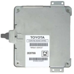
When working with immobilizer EEPROMs, sometimes the ideal way for us to program the EEPROM is to do it while it is in the circuit, as removing it, programming it, and resoldering it back to the circuit adds a bit more effort and time to complete the job.
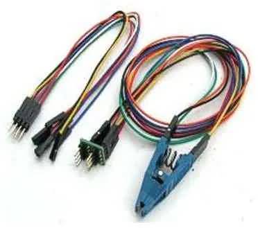
You can do this “in-circuit” on many ECMs (not all) using an SOIC-8 clip or 8 separate SMD pincers, connecting either solution over the EEPROM chip while it is in the circuit, but sometimes some inconveniences arise. These inconveniences include needing to clean the EEPROM leads of any protective silicone, glue, or resin/flux coating the ECM might have in the circuit, which can cover individual components. Another problem (for the clip) is if the EEPROM has too low a profile, making it impossible to get enough grip on the chip body to keep the clip in place.
Possible problems of using this approach
Above all, a major inconvenience of programming an EEPROM in an “in-circuit” fashion is that the microcontroller (MCU) in the ECM circuit may be sensitive to the voltages the EEPROM programmer uses to read and write the EEPROM chip. This happens often because MCU operating voltages have dropped from 5 volts to 3.3 volts, and now to as low as 1.8 volts. In these cases, the microcontroller draws enough current from the EEPROM programmer to attempt to start (run) its internal program. This situation varies from ECM to ECM and from programmer to programmer, but when it happens, it interferes with the data we are working with and corrupts it. When this happens, we get an incorrect image of the EEPROM during reading, or we program the wrong data to the EEPROM during writing.
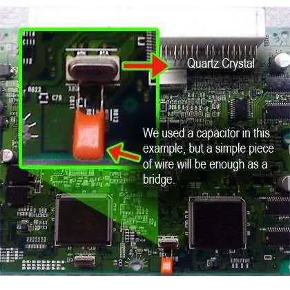
For this, we can try the common solution of disabling the MCU’s crystal oscillator to prevent it from running, or at least try to prevent it, since this does not work in all cases. You can do this by shorting the crystal oscillator with either a relatively large capacitor (in this example, a 0.1 μF capacitor) or a small jumper wire across the crystal (in parallel with it). The picture below shows how a 0.1 μF capacitor was temporarily soldered across the crystal terminals to disable it.
Other Solution
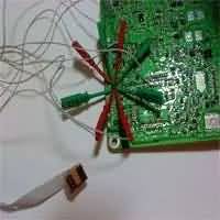
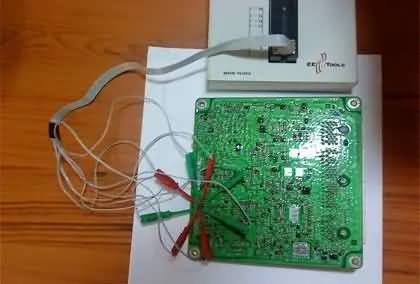
If you don’t have a SOIC-8 SMD clip to read and write the immobilizer EEPROM, or you simply don’t like that method because it’s somewhat unreliable, the picture below shows another approach. For this, you will need to build the harness or buy it preassembled, as it is available to order online.
The wires include 8 micro clips and an 8-connection dual-pin header (4 + 4) to connect it to the programmer. Once built, you can reuse it, and it will even last longer than the SOIC clip itself. If you decide to construct it yourself, be as neat as possible and use high-quality materials so you end up making a durable tool, and don’t just make a prototype like the one shown here 🙂
Online stores sell some of the equipment used for this job. For example, you can buy the SOIC-8 SMD clip, complete with its harness, ready to use from online stores.
Finally, please be careful when working with static-sensitive electronics. Always use ESD (Electrostatic Discharge) protection to avoid irreparable damage to the circuits and/or devices, especially if you live in cold, dry weather.