1992 – 1995 JDM Honda Computers Performance Chip Installation
This covers installing a chip in the 1992-1995 Honda JDM ECUs: “P72”, “P30”, and “P08”.
Installing a performance chip on 1992-1995 Honda JDM computers uses the same method as described in other posts on this website about non-JDM ECUs. You may use the search function above to find the other publications.
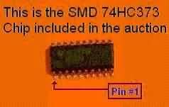
The main difference in installing JDM ECUs compared with USDM, Canadian, European, Australian, and some other non-JDM ECUs is the need to install surface-mount devices (SMDs) in the JDM versions. The same installation kit applies to the P28 and other OBD-I Civic/Integra ECUs, but the parts are smaller. These parts are: the 74HC373 latch chip, the “J1” jumper, and the two .1uf bypass capacitors, which, instead of being through-hole mounting devices, are mounted and soldered on one surface of the circuit board. They are smaller and a little bit more difficult to handle than their counterparts. Still, it is a simple job.
The resistor “R54” isn’t needed for this installation, and the two capacitors are optional. So, only the jumper “J1” and the surface-mount 74HC373 latch chip will be shown.
This is the 74HC373 SMD Chip
This job requires average electronics soldering skills. You can always bring the ECU and the new chip to any TV or electronics shop, so they can install the chip and the other parts for you. Also, verify all connections before and after soldering the socket. Be careful not to short connections while soldering or break circuit traces by overheating them.
Please note that connections above, below, and inside the circuit board are sensitive to excessive heat. Always clean the finished job with a mild solvent like isopropyl alcohol.
This installation is needed only once. After that, it’s as simple as removing one chip and inserting another if you want to switch tunings or compare chips.
If you ever want to go back to stock mode, like for emission tests, for example, please don’t uninstall anything. Just remove the jumper “J1”. Installing that jumper will switch to performance mode again, as long as the performance chip is inserted.
Your computer is located in the passenger-side kick panel or lower dash. After locating the computer in your vehicle, remove the bolts that attach it to the vehicle’s chassis and carefully disconnect the wire harnesses plugged into the ECU terminals. To disconnect the wire harnesses, push the clip on top of the plastic connectors and carefully pull the connector back.
After removing the ECU, place it on a flat table or bench and remove the bolts securing the top and bottom covers using a #2 Phillips screwdriver. Remove the bolts that secure the small board on top of the main board, and CAREFULLY flip it back, taking care not to break the flexible ribbon cable attached to it.
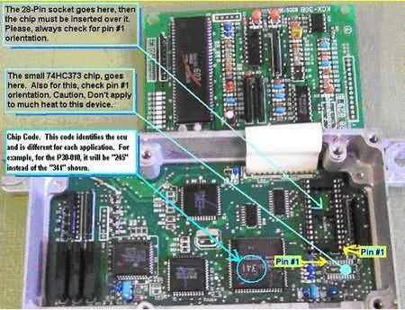
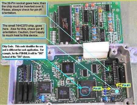
To install the chip, locate the footprints on the circuit board that match the parts to be installed (See picture above). In most cases, no parts will be installed in the targeted spots. You only need to clean the spots (remove the solder) and then solder the corresponding parts in place.
First, solder in place the 28-Pin socket and the 74HC373 small chip (SMD – Surface Mount Device).
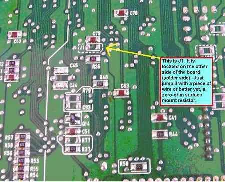
Next, flip over the ECU circuit and locate the “J1” jumper spot on that side. Bridge it with a small piece of wire or a zero-ohm surface-mount resistor (0R). A 0-ohm surface-mount resistor is the easiest solution, but a low-profile (low-height) arc-shaped solid wire could be handy if you need to quickly cut the jumper to return to stock specs. If you decide to put a switch on the ECU wall or cover, that’s fine, but keep wires short or use shielded wire to avoid electronic noise that could lock up the microcontroller and require you to turn the engine off and then on. Check the picture below for the location of “J1”.
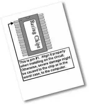
Now insert the performance chip into the 28-Pin socket. Please use the drawings above and below as a reference to make sure you install the chip correctly in the socket.
Now you are ready to put it all back together and reinstall the ECU to enjoy the new performance!