
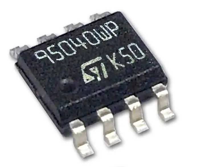

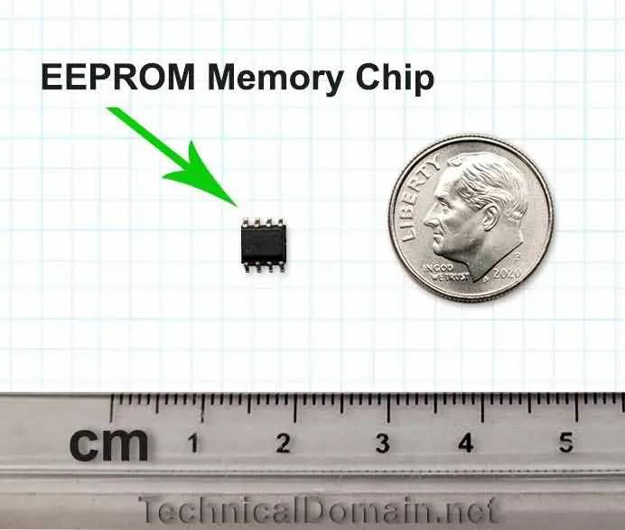
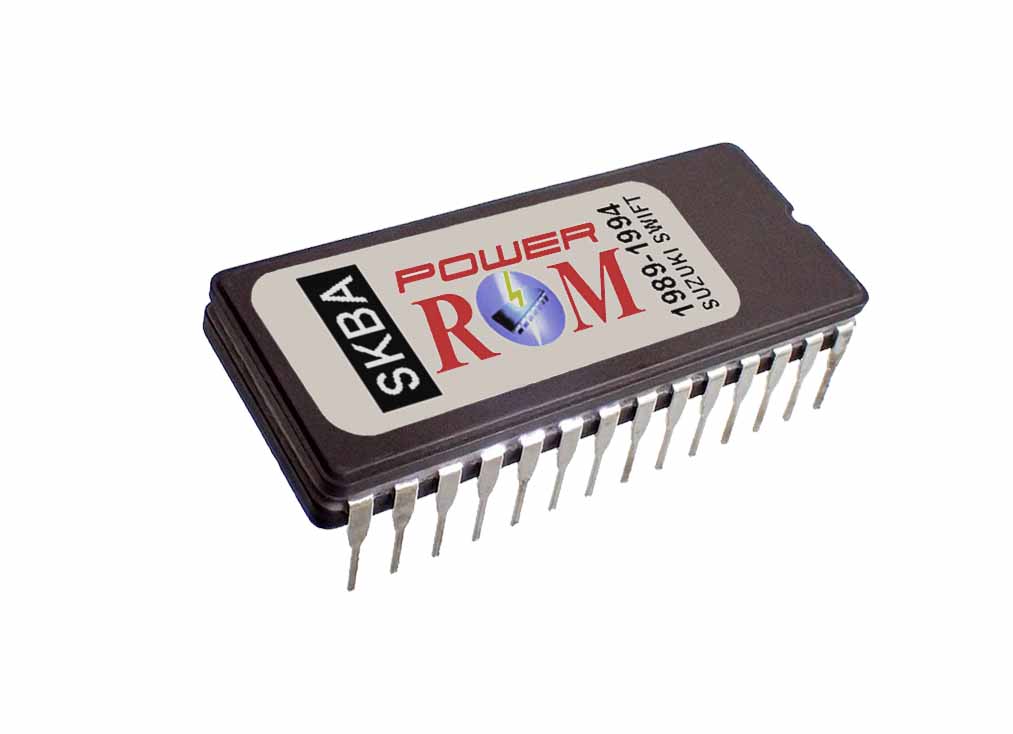
Immobilizer reset EEPROM chip (virgin chip) with your car’s VIN included for the 2005-2008 Toyota Corolla and Matrix models (1.8L VVTi, either for the automatic transmission (A/T) models, or manual transmission (M/T) models.
IMPORTANT: Even when this is an easy job to do, it is a technical job. If you do not have any experience in soldering electronic parts, please bring the job of this product to a qualified technician to do it.
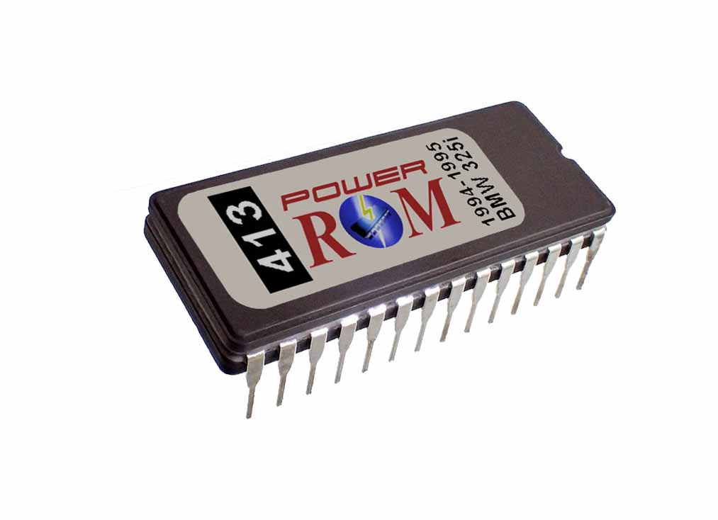
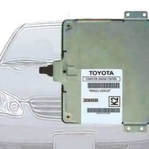
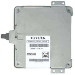
If you replace your Corolla ECM with a used one, first, you will need to adjust the immobilizer system so that the engine starts with the replacement ECM. Second, you will need to enter the VIN of your car to avoid the “VIN Mismatch” error code.
With this solution, both issues are covered, and it is faster than sending your ECM in for service.
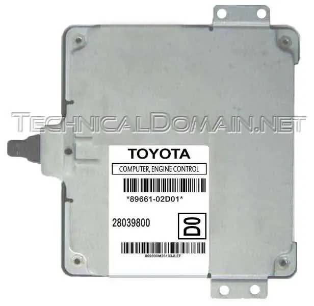
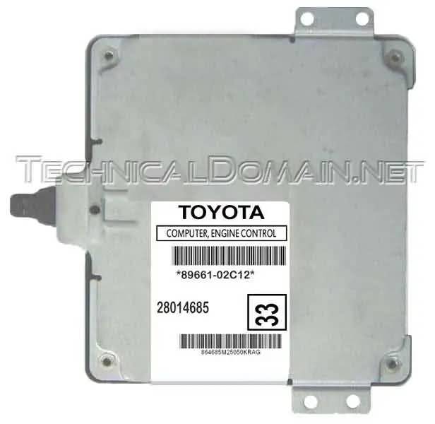
This chip will work on the following ECMs from the 2005, 2006, 2007, and 2008 Corolla and Matrix models:
| 89661-02C10 | 89661-02C11 | 89661-02C12 | 89661-02C13 | 89661-02C30 |
| 89661-02C91 | 89661-02D01 | 89661-02D02 | 89661-02D11 | 89661-02D12 |
| 89661-02D51 | 89661-02K10 | 89661-02K20 | 89661-02K21 | 89661-02K22 |
| 89661-02K23 | 89661-02K33 | 89661-02K40 | 89661-02K41 | 89661-02K42 |
| 89661-02K43 | 89661-02K50 | 89661-02K51 | 89661-02K52 | 89661-02K53 |
| 89661-02K80 | 89661-02R00 | 89661-02R01 | 89661-02R02 | 89661-02R10 |
| 89661-02R12 | 89661-02R31 | 89661-02R50 | 89661-0Z040 | 89661-0Z041 |
| 89661-0Z042 | 89661-0Z043 | 590-60782 | 590-50965 | 590-51541 |
Upon ordering, we will send you a pre-programmed chip to be installed in your ECM with the instructions for the process. The chip will contain the VIN you provide, and the programming to reset the immobilizer system of your car, allowing it to automatically register and accept your actual key(s).
We can also do the job for you in case you prefer our professional service.
NOTES:
- Please ensure that you provide the correct VIN (17 characters) in the form provided for that purpose at the last step of the checkout process.
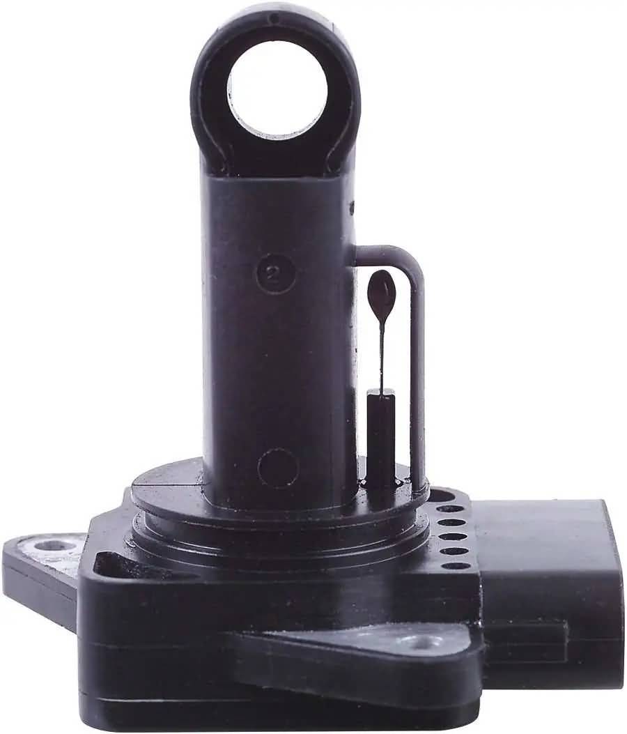
Location of the ECM in your car:

TAGS: toyota corolla immobilizer chip

Read reviews left for us, or leave your own on Trustpilot! Available in the link below:
TechnicalDomain.net Reviews
You may also check our local reviews (left for us on our website):
Reviews
There are no reviews yet.